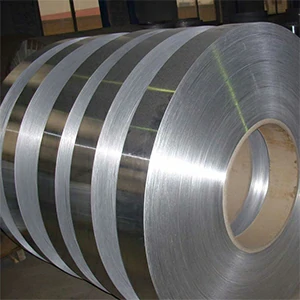
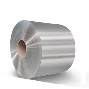
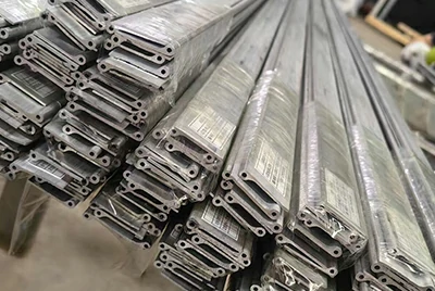
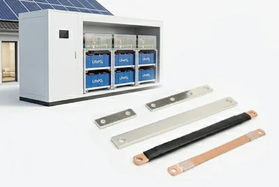
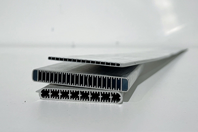
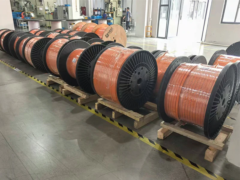
Reel-supplied insulated aluminum flat conductors combine a solid aluminum alloy core with continuous insulation and are supplied on reels for EV high-voltage power distribution and connection systems in battery packs, BJB / BDU, and the on-vehicle Charging Inlet → Battery path. They are designed for downstream busbar forming and assembly.
HENAN CHALCO offers Polymer-Insulated and Fire-Resistant Thermal-Barrier Composite insulation options. Select the insulation structure based on high-voltage insulation, thermal-protection requirements, and the actual installation location.
- Lightweight High-Current Connections
- Continuous Reel Feeding
- Standard Insulation / Fire & Thermal Protection Options
Quick Links: Polymer-Insulated Aluminum Flat Conductor | Fire-Resistant Thermal-Barrier Composite Insulated Aluminum Busbar
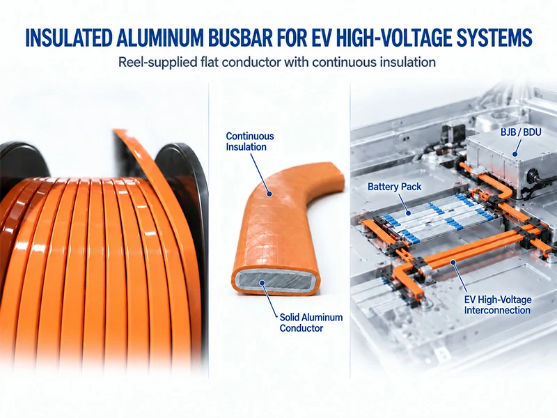
Two Insulation Designs for Different EV High-Voltage Requirements
Reel-supplied insulated aluminum flat conductors are available with two insulation designs. Both use a solid aluminum alloy flat conductor as the current-carrying core; the main difference is the insulation system:
Polymer-Insulated Aluminum Flat Conductor
Polymer-Insulated design focuses on high-voltage electrical insulation and conductor protection; Fire-Resistant Thermal-Barrier Composite design adds fire and thermal protection beyond basic insulation for EV high-voltage connections where additional thermal protection is required.
The polymer-insulated type uses PA12, PVC, PE, or other polymer insulation over a solid aluminum alloy flat conductor. Supplied on reels, it provides high-voltage electrical insulation and conductor protection; downstream processing requirements are confirmed against the customer's process.
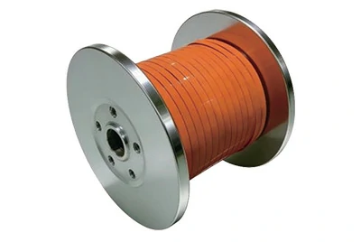
Basic Specifications
Aluminum alloy: 6101-T61 / T63 / T64 / T65
Cross-sectional area: 120 / 150 / 180 / 200 mm²
Insulation materials: PA12 / PVC / PE
Insulation thickness: 0.5 mm and above, subject to project evaluation
Supply form: continuously insulated conductor supplied on reels
Product Features
- Solid aluminum alloy conductor balances current-carrying capability and lightweight design;
- Continuous polymer coating provides high-voltage electrical insulation and conductor protection;
- Continuous reel feeding supports high-volume busbar production;
- Insulation materials can be selected to match temperature, environment, and processing requirements;
For EV busbar projects focused on high-voltage insulation, current-carrying capability, lightweight design, and high-volume production, the polymer-insulated type is typically the first option to evaluate.
Fire-Resistant Thermal-Barrier Composite Insulated Aluminum Busbar
The fire-resistant thermal-barrier type adds fire-/thermal-barrier functional layers plus outer insulation around the same solid aluminum alloy flat conductor. This multilayer insulated aluminum busbar structure is intended for high-voltage connection areas exposed to high temperatures, flame, or nearby heat sources.
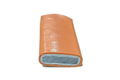
Basic Specifications
Aluminum alloy: 6101-T61 / T63 / T64 / T65
Cross-sectional area: 120 / 150 / 180 / 200 mm²
Insulation structure: multilayer fire-resistant thermal-barrier composite
Fire-resistant layer: fire-/thermal-barrier material
Outer insulation: polymer protective insulation
Supply form: composite-insulated conductor supplied on reels
Product Features
- Adds fire resistance and thermal-barrier functionality to high-voltage electrical insulation;
- Provides added thermal protection near cells, modules, or other potential heat sources;
- Maintains continuous multilayer insulation while retaining reel-supplied form;
Where high temperatures, flame exposure, or additional thermal protection are concerns, the fire-resistant thermal-barrier composite type should be evaluated.
Which Insulation Design Fits the Operating Environment?
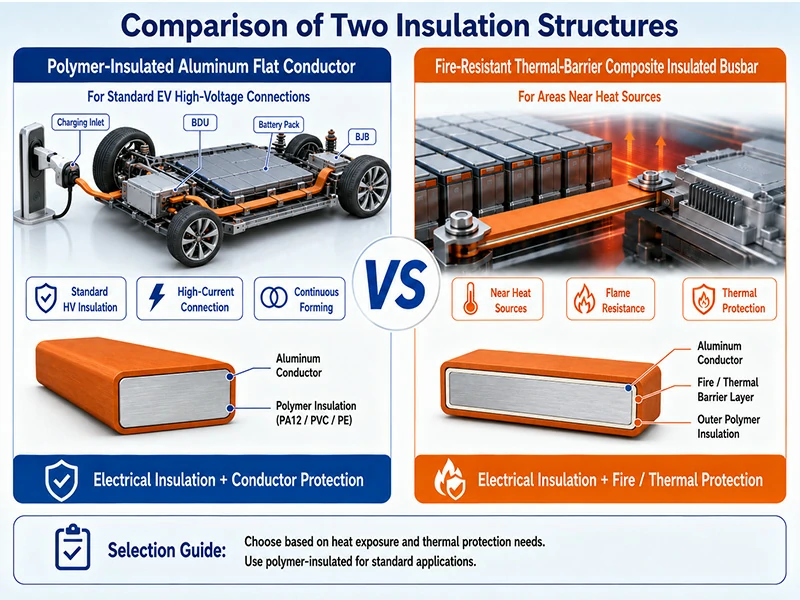
The choice depends on whether the insulation system must provide additional thermal protection. For Battery Pack, BJB / BDU, and Charging Inlet → Battery applications, the actual installation location and thermal risk must also be considered.
Choosing Insulation for EV High-Voltage Busbar Applications
Selection should be based on the busbar's actual location, interfaces, temperature rise, and thermal risk.
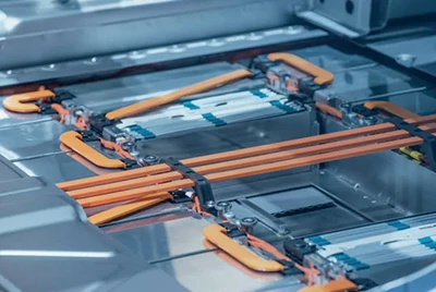
Battery Pack High-Voltage Busbar Connections
Inside the battery pack, busbars connect modules, high-voltage power distribution zones, and pack output terminals. Key selection factors include routing, current load, available space, and distance from cell / module heat sources.
Key checks: continuous current, cross section and path length; distance from cell / module; bend and installation space; and whether the route passes through high-thermal-risk areas.
For standard current-carrying and insulation zones, evaluate the polymer-insulated type first. Where the busbar is close to cells / modules, potential heat sources, or areas with additional fire/thermal-protection requirements, evaluate the fire-resistant thermal-barrier composite type.
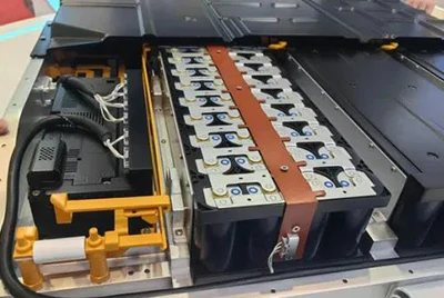
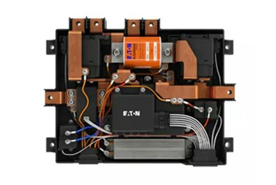
BJB / BDU Power Distribution Busbar Connections
BJB / BDU assemblies integrate high-voltage components such as contactors, fuses, current sensors / shunts, and terminals. Key concerns are interface density, localized temperature rise, and forming/assembly within tight spaces.
Key checks: component interfaces and hole-position tolerances; contact resistance and localized temperature rise; copper-to-aluminum interfaces; and local space and heat-source conditions.
Where high current, dense interfaces, and terminal-area processing dominate, evaluate the polymer-insulated type first. If clear heat sources or additional thermal-protection requirements are present, evaluate the fire-resistant thermal-barrier composite type.
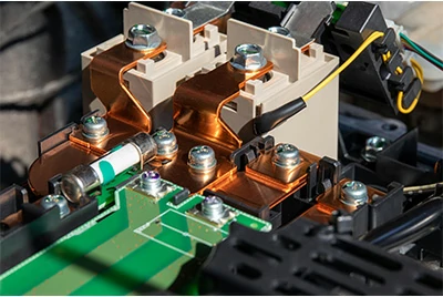
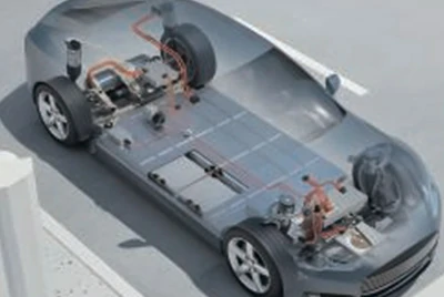
EV Charging Busbar: Charging Inlet → Battery
This section refers specifically to the on-vehicle high-voltage charging busbar path from the charging inlet to the battery, not busbars inside charging stations.
Key considerations are temperature rise along the full path under sustained high current, the connector-to-busbar interface, and in-vehicle routing; confirm charging current and duration, conductor cross section and path length, interface temperature rise, and heat-source distribution.
For standard in-vehicle high-voltage environments, evaluate the polymer-insulated type first. If any section of the routing runs close to the battery, power electronics, or other high-temperature areas, evaluate the fire-resistant thermal-barrier composite type based on actual heat exposure.
Quick Selection Guide
| Engineering Condition | Recommended Evaluation Direction |
| Standard high-voltage routing focused on insulation, current-carrying capability, and weight | Polymer-Insulated |
| Dense BJB / BDU interfaces requiring bending, stripping, and termination | Polymer-Insulated |
| Near cell / module or a defined heat source | Fire-Resistant Thermal-Barrier Composite |
| Fire-resistance, thermal-barrier, or flame-exposure requirements | Fire-Resistant Thermal-Barrier Composite |
| One routing crosses areas with different thermal-risk levels | Re-evaluate based on the highest-risk section |
| Charging Inlet → Battery | Assess based on current, interface temperature rise, and thermal environment |
Next, confirm how this reel-fed insulated aluminum conductor fits the customer's straightening, cutting, stripping, bending, and terminal-connection processes.
Downstream Processing of Reel-Fed Insulated Aluminum Busbar Material
After selecting the insulation design, confirm that the reel-fed material is compatible with the customer's existing busbar processing line.
Typical process:
Reel Feeding → Straightening → Cutting → Stripping → Forming → Terminal Preparation
For pre-insulated aluminum busbar material, the key issue is not the sequence of operations itself, but whether reel condition, conductor geometry, and insulation structure remain compatible throughout continuous processing.
Reel Feeding and Straightening
Reel dimensions, winding direction, winding pattern, straightness, and twist all affect unwinding, straightening, and automatic feeding.
For coiled insulated aluminum busbar material, reel condition must match the customer's existing unwinding and straightening equipment. The reel is not just packaging; it is a production input for continuous processing.
Stripping and Bending/Forming
Pre-insulated aluminum busbar material requires simultaneous consideration of conductor forming and insulation deformation.
Bending performance is mainly influenced by:
- Alloy temper and conductor cross section;
- Width-to-thickness ratio and edge geometry;
- Bend direction and radius;
- Insulation material and construction.
For the polymer-insulated type, focus on wrinkling, cracking, and insulation continuity after bending; the fire-resistant thermal-barrier composite type also requires attention to synchronized deformation of the multilayer structure and interlayer integrity.
Terminal areas typically require local insulation stripping, so define the strip location, length, boundary, and allowable residue.
Terminal-Area Processing and Joining
The finished busbar needs exposed conductive connection areas and, depending on the design, may require hole processing, terminal assembly, welding, or mechanical joining.
Confirm in advance:
- Insulation termination position and exposed length;
- Punching / drilling area;
- terminal geometry;
- Aluminum surface condition;
- Final joining method.
For the fire-resistant thermal-barrier composite type, also define how the functional layers terminate in the terminal area to avoid affecting the connection interface.
What Should Be Confirmed Before Processing?
At the project outset, provide:
- Busbar drawing or target routing
- Reel dimensions, winding direction, and per-reel requirements
- Bend radius and direction
- Strip location and length
- Hole positions and terminal geometry
- Welding or mechanical joining method
These inputs determine whether reel-fed material can reliably transition from a continuous coil to a formed EV high-voltage busbar.
Once processing conditions are defined, the next step is to verify whether, after feeding, bending, stripping, and terminal-area processing, dimensions, insulation structure, and key performance remain stable.
What Should Be Verified After Busbar Processing?
After bending, stripping, and terminal-area processing, reel-supplied insulated aluminum busbar should be verified to ensure that the insulation structure, formed dimensions, and connection areas remain stable, so issues are identified before downstream assembly or performance testing.
Key Validation Items
- Bend integrity: check for insulation cracking, wrinkling, or visible damage;
- Stripping and terminal condition: confirm strip boundaries, insulation residue, and exposed conductor surfaces meet connection requirements;
- Formed dimensions: confirm critical dimensions and interface positions meet assembly requirements;
- Electrical and temperature rise: verify resistance and temperature rise under sustained current in the actual connection.
For the Polymer-Insulated design, focus on insulation integrity after bending, stripping condition, and temperature rise; Fire-Resistant Thermal-Barrier Composite also requires confirmation that the multilayer structure shows no obvious delamination, the fire-/thermal-barrier functional layers remain continuous after forming, and thermal-protection performance is assessed using the actual formed sample.
Fire resistance, flame retardancy, and thermal insulation are different performance requirements. Test results should be interpreted together with the sample construction, test temperature, exposure time, and measurement location; a single flame-retardant rating cannot substitute for fire-resistance or thermal-barrier validation of the complete busbar.
From Sample Validation to Volume Production
For new projects, HENANCHALCO can first provide samples based on the confirmed product configuration and processing requirements, allowing the customer to use actual equipment for bending, stripping, termination, and required performance validation.
After sample validation, pilot-lot and production-volume requirements can be confirmed. This helps identify mismatches between the material and the customer's process conditions before scale-up, reducing downstream scrap and production-launch risk.
For volume production, the confirmed conductor, insulation structure, reel requirements, and key processing conditions can serve as the supply baseline, supported by batch / reel-number traceability, inspection records, and defined change-control requirements.
HENANCHALCO can coordinate the manufacturing source, batch information, and scope of available inspection and documentation according to project requirements, helping carry the requirements confirmed during sampling into subsequent volume production.
[Pre-Launch Hard Gate | Project Introduction and Documentation] Confirm sample availability for both insulation structures, actual production-source coordination, batch / reel-number traceability, key change-control confirmation, and the actual availability of material certificates, dimensional inspection, performance test records, and other required documents.
Which Projects Are Best Suited to Reel-Supplied Insulated Aluminum Busbar?
Reel-supplied insulated aluminum busbar is best suited to EV high-voltage projects with in-house high-volume processing of rigid, flat busbar parts using continuous reel material for cutting to length, stripping, bending, and terminal-area processing. Selection depends not only on material performance, but also on the customer's production model and final part configuration.
Better Suited for Evaluation
- Rigid, flat EV high-voltage busbar routing;
- Capability for continuous feeding, bending, and terminal-area processing;
- Stable volume demand for similar busbar parts;
- Ability to validate actual processing and performance using samples;
Reconsider the Supply Approach
- The project requires continuously flexing or dynamically moving connections better suited to a high-voltage cable or charging harness;
- The customer only purchases fully formed and terminated 3D busbar assemblies;
- No capability for stripping, termination, or joining of aluminum conductors;
- Only small quantities of complex parts are required, limiting the value of continuous reel processing;
- Packaging space or interface conditions cannot accommodate the aluminum flat-conductor cross section.
The value of reel supply is strongest for repeatable processing, stable routing, and high-volume production. If the project does not meet these conditions, another material form or finished-part supply model may be more appropriate.
Frequently Asked Questions
How Is the Minimum Bend Radius Determined?
There is no single minimum bend radius that applies to all sizes. It should be confirmed based on alloy temper, conductor width-to-thickness ratio, bend direction, target angle, and insulation structure, and should be validated by forming actual samples.
Does the Fire-Resistant Thermal-Barrier Type Retain Thermal Protection After Bending?
It should be validated using the actual formed sample. Bending can affect stress distribution and interlayer condition in a multilayer structure, so test results from straight material cannot fully represent performance in the final busbar condition.
How Is Insulation Handled in the Terminal Area?
Insulation is typically removed locally in terminal, welding, or mechanical-connection areas. The location and stripped length should be defined based on terminal geometry, hole position, exposed conductor length, and joining method. For the fire-resistant thermal-barrier type, the termination position of the functional layers should also be confirmed.
What Test and Quality Documents Can Be Provided?
Depending on the specific product, manufacturing source, and project requirements, available documents may include material certificates, dimensional inspection records, performance test records, and batch / reel-number traceability. Additional automotive project documentation should be confirmed separately during project introduction.
Send Your Drawing or Conductor Requirement
For initial evaluation, you do not need to define every processing parameter at once. You can start by providing:
- Application / Installation Position
- Drawing or Width × Thickness / Target Cross-Section
- Insulation Requirement
If available, estimated volume, bending, stripping, terminal, or reel requirements can also be included.
HENANCHALCO will use this information to confirm the appropriate product configuration and sample-evaluation requirements, then define the detailed technical and supply requirements.