In semiconductor packaging, wire bonding and ribbon bonding (also called bonding band) are the two mainstream ways of connecting the die pad to the leadframe or substrate. The difference lies in the cross-sectional shape of the conductor — one is a round wire, the other a flat ribbon.
This article covers die-to-package bonding materials in the form of bonding wire and bonding ribbon; it does not cover electrical grounding straps, photovoltaic PV ribbon, or grounding braids.
The sections below walk through current, heat dissipation, reliability, equivalence conversion, cost, and applications to help you decide between round wire and flat ribbon in power modules.
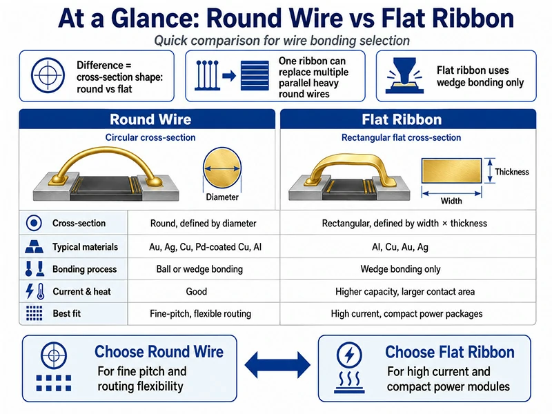
At a glance: round wire vs flat ribbon
- The difference between wire and ribbon is cross-sectional shape (round vs flat), not process; ribbon can only be wedge bonded.
- One ribbon can replace multiple thick round wires in parallel, reducing the number of bond points.
- High-current, small power packages favor ribbon; fine-pitch and any-direction routing favor round wire.
| Dimension | Round wire | Flat ribbon |
| Cross-section | Round cross-section, described by diameter | Flat rectangular cross-section, described by width × thickness |
| Typical materials | Au, Ag, Cu, Pd-coated Cu, Al | Al, Cu, Au, Ag |
| Bonding process | ball or wedge bonding | wedge bonding only |
| Current & heat | Good | Higher, with a larger contact area |
| Best fit | Fine-pitch, any-direction routing | High current, small power packages |
What is wire bonding in semiconductor packaging?
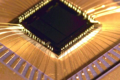
Wire bonding is a packaging interconnect technology that uses fine metal wire, driven by ultrasonic, thermosonic, or thermocompression energy, to connect the die pad to the leadframe or substrate.
Common wire materials include gold, aluminum, copper, and silver, with diameters ranging from fine wires of a dozen-plus microns to heavy wires of several hundred microns.
To this day it remains the most mature and widely used die-level interconnect method — industry sources generally hold that most die-to-package connections worldwide are still made by wire bonding. Even against alternatives such as flip chip, it remains the workhorse for low-to-medium pin-count, power, and discrete device packages.
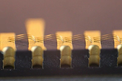
Yet the conductor used in wire bonding is not limited to a round cross-section. Flatten the round wire into a rectangular one and you get ribbon bonding — still ultrasonic bonding, only with a different conductor form.
That difference in shape is precisely what drives the performance and process trade-offs that follow.
Round wire vs flat ribbon — what's the real difference?
The most common misconception is treating ribbon bonding as a separate "process". In fact, the difference between it and round wire bonding is the material form, not the process route.
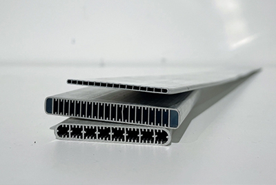
Round wire has a circular cross-section described by diameter, spanning a wide range from fine wire to heavy wire. Flat ribbon has a rectangular cross-section described by two dimensions, width × thickness — for example 1.0 mm × 0.1 mm.
Both are ultrasonic bonding materials; ribbon is not some brand-new process, just a set of new characteristics that come from "flattening the wire".
The key point: once the cross-sectional shape changes, the bonding process it can use, the current it can carry, and the packages it suits all change with it.
Round wire has one adjustable parameter (diameter), while ribbon has two (width and thickness), giving more design flexibility — a point that becomes very clear in the equivalence conversion later.
A quick note on naming: ribbon also appears in the literature as bonding band or ribbon wire — all referring to the same flat bonding ribbon, not to be confused with photovoltaic PV ribbon.
How the bonding process links to material choice
To understand the wire-versus-ribbon trade-off, start with one asymmetric fact: ribbon can only be wedge bonded, while round wire works with both ball bonding and wedge bonding.
At the start of each bonding cycle, ball bonding melts the wire tail into a ball (free-air ball, FAB) with an electric spark, then bonds it as the first bond. It is non-directional — the second bond can be placed in any direction — and fast, mainly used for fine gold, copper, palladium-coated copper, and silver wires, and it usually requires elevated temperature.
Wedge bonding forms no ball; it bonds directly under pressure and ultrasonic energy, with a low loop and a directional constraint, and can bond round wire of any size as well as ribbon. Aluminum wire and aluminum ribbon can be bonded ultrasonically at room temperature.
Why can ribbon only be wedge bonded? Because its flat cross-section cannot be bonded omnidirectionally on a ball bonder the way round wire can — it must be bonded directionally by a dedicated wedge tool. In other words, the combination "ribbon + ball bonding" simply does not exist physically.
This in turn defines the material pool: with wedge bonding you get aluminum wire and all ribbon types; with ball bonding you get fine-diameter precious-metal or copper round wires.
For a deeper look at the two processes themselves, see our Ball Bonding vs Wedge Bonding guide.
Where ribbon wins — current, heat, and reliability
In high-current applications, ribbon's advantage goes beyond simply "a larger cross-section" — there is a more specific mechanism behind it.
More uniform current entry into the die. Published technical research points out that when multiple round wires are paralleled on the same pad, their bond contact areas are separate and discontinuous; heavy current entering the die from these scattered points can create local differences in heat dissipation and electric field. A ribbon, by contrast, provides one continuous large contact area, so current enters the die more evenly.
For high-power, high-current devices, a continuous large bonded area can often carry more current.
Better heat dissipation. The larger contact and surface area helps dissipate heat — valuable in power devices operating continuously at high current.
Lower parasitic inductance. In RF and high-frequency paths, the ribbon's low inductance is a secondary but real advantage.
Durability under temperature cycling. Published research shows that under temperature cycling, the bond life of an equivalent aluminum ribbon can reach roughly 2.17 times that of equivalent aluminum wire (comparing Al ribbon and Al wire of comparable current-carrying capacity).
For reference, published data also indicate that at a loop length of about 1 cm, a 300 µm aluminum wire carries roughly 25 A and a 500 µm wire roughly 60 A — figures that vary with test conditions and are for order-of-magnitude reference only.
These advantages are most visible in high-current-density IGBT / SiC power modules.
One ribbon, how many wires? the equivalence logic
One of the most practical questions engineers ask: "I currently use N heavy aluminum wires — how many ribbons would replace them?" To answer it, understand the conversion logic first rather than memorizing a table.
The essence of the conversion is equal resistance over equal length, determined by cross-sectional area × resistivity. A ribbon's width × thickness cross-section can equal the combined cross-sections of several round wires — match the cross-section and the resistance over the same length matches too.
Published conversion data indicate that an aluminum ribbon with a width-to-thickness ratio of roughly 10:1 can replace about 12 aluminum wires whose diameter equals the ribbon thickness, or about 8 copper wires. For example, a 1.0 mm × 0.1 mm aluminum ribbon has a cross-section of about 100,000 µm², while a 100 µm aluminum round wire has about 7,854 µm² — a ratio of roughly 12.7, consistent with the figure above.
A worked example: Suppose you currently use four 380 µm aluminum wires, a total cross-section of about 0.454 mm². A single 2.0 mm × 0.25 mm aluminum ribbon (0.5 mm² cross-section) is then sufficient as an electrical equivalent. The steps are simple — sum the wire cross-sections, pick a ribbon of equal or slightly larger cross-section, then verify against the package conditions.
Quick geometric equivalence (derived from cross-sectional area, rounded):
| Ribbon size | ≈ 200 µm Al wire | ≈ 300 µm Al wire | ≈ 380 µm Al wire |
| 1.0 mm × 0.1 mm | about 3 | about 1 | about 1 |
| 1.5 mm × 0.15 mm | about 7 | about 3 | about 2 |
| 2.0 mm × 0.2 mm | about 13 | about 6 | about 3–4 |
(Computed from cross-sectional geometry; actual selection must still account for current and the process window.)
Different materials replace different wire counts because their resistivities differ: ρ_Al ≈ 2.7, ρ_Cu ≈ 1.7, ρ_Au ≈ 2.3 ×10⁻⁶ Ω·cm. Copper's lower resistivity means a copper ribbon of the same cross-section replaces a different number of wires than an aluminum one.
The practical gain from the conversion is a lower bond count — fewer potential failure interfaces and a faster bonding cycle.
A reminder, though: the equivalence conversion is only the starting point of "electrical equivalence" — final selection must still account for loop height, pad size, and the process window.
Does ribbon bonding actually lower your cost?
Does switching to ribbon actually save money? The answer is not a simple "yes" or "no" — it depends on the combination of several cost factors.
Material cost
Unit costs differ markedly across gold, silver, copper, and aluminum bonding wires — gold is the highest, while copper and aluminum are more economical. Material choice is itself a cost lever, considered on top of the wire-versus-ribbon form choice.
Bond count and throughput
One ribbon replacing several wires means fewer bonding cycles and a faster bonding rhythm, cutting bonding labor time per package. This is ribbon's most direct source of economy in high-volume production.
Reliability cost
Fewer bond interfaces mean fewer potential failure points, which over time helps reduce rework and failure-related costs.
The one-off investment on the other side
Ribbon requires dedicated wedge tools and a deep-access bondhead, so adoption carries a one-time equipment and tooling investment. For small volumes, or where a mature heavy-wire line already exists, switching may not pay off.
So whether it saves money comes down to the total cost of ownership — materials, labor, yield, and equipment amortization combined — not the material unit price alone. Whether switching is worthwhile varies with package type, production volume, and the current state of your line.
Which applications use wire vs ribbon?
Current and pitch requirements differ by application, and so does the right choice — use this to locate yours quickly:
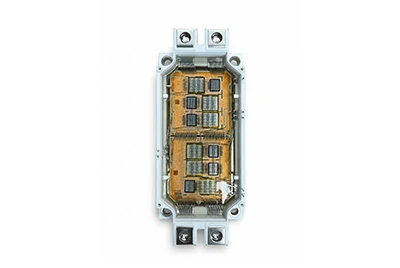
Power modules (IGBT / SiC / DBC)
High-current paths — the home turf of heavy aluminum wire and aluminum ribbon.
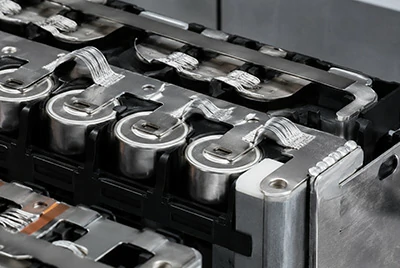
Automotive & EV
Motor-control modules, battery modules, and CCS high-current interconnects, where ribbon's reliability and cycle-time advantages stand out.
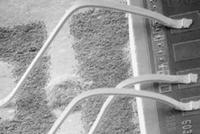
RF / Microwave
High-frequency signal paths, where the ribbon's low inductance is a secondary advantage.
LED / Optoelectronics
Mostly fine round wire with ball bonding; high-power LEDs show a trend toward ribbon.
IC / Logic / MEMS
Fine pitch and high pin counts — the home turf of fine round wire.
The application sets the current and pitch requirements, which in turn decide wire or ribbon. For more background on power module scenarios, see our semiconductor packaging applications page.
How to choose — round wire or ribbon?
Having covered the advantages, the full picture matters too: ribbon is not best at everything — in many situations round wire remains the right choice.
Where round wire still wins.
Ribbon is directional — it cannot be routed omnidirectionally like round wire, so round wire is more flexible for sharp bends or complex routing; fine-pitch ICs and signal lines remain round wire territory. Ribbon also needs dedicated wedge tools and a deep-access bondhead, so not every line can adopt it plug-and-play.
Failure modes to face squarely.
Published failure analyses point out that second-bond lift and heel crack are real failure modes for ribbon, and that ribbon is more sensitive to the bonding process window and interface cleanliness. This is not a case against ribbon — it is a reminder that the corresponding process controls must be in place.
Decision quick reference:
| Your scenario | Better fit | Why |
| High current / small power package | Ribbon | Continuous large contact area; better current and heat |
| Fine-pitch signal IC | Round wire | Fine-pitch routing capability |
| Any-direction / complex routing | Round wire | No directional constraint |
| Mature heavy-wire line, modest volume | Depends | Switching carries one-time equipment and tooling costs |
| High-frequency / RF path | Ribbon worth prioritizing | Low parasitic inductance |
Ultimately, selection is about matching the scenario — not about ribbon being unconditionally better than wire.
Qualifying the switch — bond testing and a practical checklist
Once you decide to trial ribbon, you still need to know how to verify bond quality and what to check before adoption.
How bond strength is verified.
Two mainstream methods: the wire pull test (destructive pull, assessing loop and bond strength) and the bond shear test (shear force, assessing the bonded interface).
Ribbon bonds, with their large contact area, are mostly evaluated by shear/push testing, while round wire relies mainly on pull testing. Test methods can follow standards such as ASTM F459 and JEDEC JESD22-B116A (check the current revision before citing).
Note that these tests answer the question of "bond strength"; they complement, rather than replace, sampling checks of the material's own breaking load and elongation.
Pre-switch evaluation checklist:
- Can the pad size and layout accommodate the ribbon width and the wedge imprint;
- Does the bonder have a deep-access bondhead and the matching wedge tools;
- Can the die attach layer (soft solder / solder paste / silver epoxy) withstand the higher ultrasonic energy of ribbon bonding;
- Do the loop height and in-package clearance fit;
- Reliability verification plan: temperature cycling / power cycling plus pull / shear sampling;
- Supply chain: do the ribbon sizes and spool format match your feeding system.
Materials at a glance — wire and ribbon options
With the framework in place, here are the materials available and how each is positioned.
Bonding wire:
- Gold: highly reliable, the mainstay of ball bonding, with slow intermetallic growth at the interface.
- Silver alloy: excellent electrical and thermal conductivity, a common alternative direction to gold wire.
- Copper / Pd-coated Copper: the cost-versus-reliability balance; copper bonding needs an inert atmosphere.
- Aluminum: the wedge-bonding mainstay for power devices; bonds ultrasonically at room temperature.
Bonding ribbon:
- Aluminum: the mainstay of high-current interconnects in power modules.
- Copper / Gold / Silver: options for different conductivity and reliability needs.
Henan Chalco supplies both bonding wire and bonding ribbon across the materials above; bonding ribbon is available in multiple width × thickness sizes.
For specifications, see the Aluminum Bonding Wire, Gold Bonding Wire, Copper / Pd-coated Copper Bonding Wire, Silver Bonding Wire, and Bonding Ribbon product pages.
Semiconductor bonding wire
Gold bonding wire
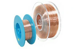
Copper bonding wire
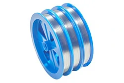
Aluminum bonding wire
Silver alloy bonding wire
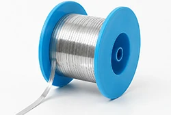
Semiconductor bonding ribbon
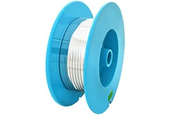
Aluminum bonding ribbon
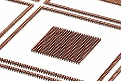
Copper pillar
Semiconductor sputtering target materials
Frequently asked questions
What is wire bonding in semiconductor packaging?
Wire bonding uses fine metal wire, driven by ultrasonic, thermosonic, or thermocompression energy, to connect the die pad to the leadframe or substrate. It is the most mature and widely used die-level interconnect method, commonly using gold, aluminum, copper, or silver wire.
What is the difference between wire bonding and ribbon bonding?
The difference is the conductor's cross-section: wire is round, ribbon is flat rectangular. Ribbon can only be wedge bonded, offers a larger contact area and higher current capacity, and is mostly used in high-current power packages; round wire suits fine pitch and any-direction routing.
How many wire bonds can one ribbon replace?
As an order of magnitude, an aluminum ribbon with a width-to-thickness ratio of about 10:1 can replace roughly 12 aluminum wires whose diameter equals the ribbon thickness (the exact count varies with size and material). The conversion is based on equal resistance over equal length, i.e. equivalent cross-section — see the equivalence section above.
Is ribbon bonding more reliable than heavy wire bonding?
Under temperature cycling, an equivalent aluminum ribbon typically outlasts equivalent aluminum wire (published research puts it at roughly 2.17×). But ribbon has failure modes of its own, such as second-bond lift and heel crack, and needs the corresponding process controls.
What is the difference between ball bonding and wedge bonding?
Ball bonding melts the wire tail into a ball before bonding — non-directional and fast, for fine round wire. Wedge bonding forms no ball, with a low loop and a directional constraint, and can bond both round wire and ribbon. See our Ball Bonding vs Wedge Bonding guide.
What is the difference between wire bonding and flip chip?
In wire/ribbon bonding the die faces up and is connected to the frame by metal wires; in flip chip the die is flipped and interconnected directly through bumps or solder balls, with no wires. This article focuses on the wire-versus-ribbon choice within the wire bonding family. In LED and similar applications each approach has its place — see LED packaging bonding wire.
Is bonding ribbon the same as bonding band or PV ribbon?
Bonding ribbon and bonding band are two names for the same flat ribbon used in die bonding. It is not the same thing as photovoltaic PV ribbon (solar tabbing ribbon) or electrical grounding straps — the uses and specifications differ.