During semiconductor packaging, chips require reliable electrical connections to transmit signals and conduct current to external circuits. Due to variations in chip size, power requirements, and package structures, the industry typically employs different bonding processes and corresponding bonding materials.
Wire bonding is one of the most widely used interconnection technologies in semiconductor packaging. It connects chip pads to package leads, substrates, or other conductive structures using semiconductor bonding wires or bonding ribbons.
Based on connection methods and application needs, the semiconductor industry primarily uses two bonding techniques:
- Ball Bonding
- Wedge Bonding
These two processes correspond to different material systems:
| Bonding Method | Common Materials | Typical Applications |
| Ball Bonding | Gold Bonding Wire, Copper Bonding Wire | IC Packaging, Memory Devices, LEDs, Precision Electronic Components |
| Wedge Bonding | Aluminum Bonding Wire, Aluminum Ribbon | IGBTs, Power Modules, Electric Vehicle Electronics, Power Systems |
Therefore, when selecting semiconductor bonding materials, customers typically match appropriate bonding processes and materials based on their product type, packaging method, and electrical performance requirements.
This article introduces the working principles, applicable materials, and selection methods for Ball Bonding and Wedge Bonding across different application scenarios. This helps customers better understand the compatibility between semiconductor bonding materials.
2. Ball Bonding: Process, Materials, and Applications
What is Ball Bonding?
Ball bonding is one of the most widely used bonding methods in semiconductor packaging. It primarily connects chip pads to package leads, substrates, or other conductive structures using fine metal wires to enable electrical signal transmission.
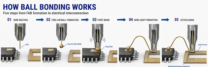
In the ball bonding process, a metal ball is first formed at the end of the bonding wire via Electrical Flame-Off (EFO). The metal ball is then connected to the chip pad using heat, pressure, and ultrasonic energy. Subsequently, wire loop control forms the connection path, completing the second bond.
Basic Steps of Ball Bonding
1. Wire Melting
High temperatures generated by electrical discharge melt the wire end, forming a spherical structure.
2. Free Air Ball Formation
Surface tension causes the molten metal droplet to form a regular spherical shape, known as the Free Air Ball (FAB).
3. First Bond Formation
A capillary tool presses the metal ball onto the chip pad surface. Heat, pressure, and ultrasonic vibration create a stable connection.
4. Wire Loop Formation
The bonding tool moves and controls the wire shape to form a loop height and path that meet package design requirements.
5. Second Bond Formation
A second bond is formed at the other end of the wire, connecting the chip to the lead frame, substrate, or other external connection areas.
Ball bonding is mainly applied to semiconductor products requiring fine wire connections, small pad pitches, and high-density packaging. Therefore, it is widely used in IC packaging, memory devices, LED packaging, and other precision electronic components.
Materials Used for Ball Bonding
Ball bonding typically uses fine metal wires with good conductivity, ductility, and bonding stability. Material selection depends primarily on the semiconductor device structure, packaging requirements, electrical performance needs, and cost factors.
Currently, the most common materials used in ball bonding include:
-
 Gold Bonding Wire
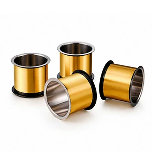
Due to its excellent ductility and mature bonding application experience, gold wire is widely used in ball bonding. In semiconductor packaging applications requiring fine pitch and high-precision connections, gold wire meets micro-connection needs through stable material properties. Typical applications cover IC packaging, LED packaging, and RF devices.
-
 Copper Bonding Wire
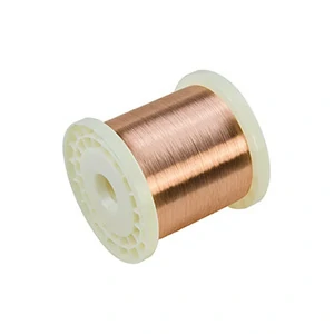
With higher conductivity and more advantageous material costs compared to gold, copper bonding wire has become an important choice in modern semiconductor packaging. It suits application scenarios requiring improved electrical performance while optimizing packaging costs. Typical applications cover advanced IC packaging and semiconductor devices.
For fine-wire ball-bonding projects, silver alloy bonding wire can also be evaluated as an alternative to gold or copper wire, depending on the package structure, bonding conditions, and reliability requirements.
Wedge Bonding: Process, Materials, and Applications
What is Wedge Bonding?
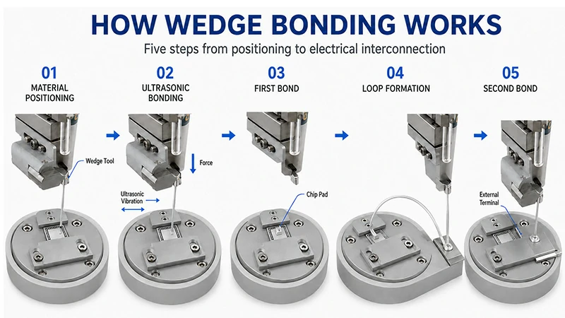
Wedge bonding is another critical bonding method in semiconductor packaging. It primarily uses a wedge tool to apply pressure to metal wires or ribbons, combined with ultrasonic energy, to form stable connections between the material and chip pads, lead frames, or other conductive structures for electrical transmission.
Unlike ball bonding, wedge bonding does not form a free air ball at the wire end. Instead, the wedge tool directly crimps the material surface. Ultrasonic vibration generates friction, creating a solid-state connection on the metal surface.
Wedge bonding is typically suitable for power semiconductor packaging requiring higher current carrying capacity, larger connection areas, and long-term reliability. Therefore, it is widely used in IGBT modules, MOSFET power devices, new energy vehicle power modules, power conversion systems, and industrial power electronics.
Compared to ball bonding, which is mainly used for fine-pitch IC packaging, wedge bonding focuses more on connection strength, current transmission capability, and reliability under power device operating conditions.
Basic Steps of Wedge Bonding
1. Material Positioning
The bonding wire or ribbon is placed at the specified position on the chip pad or connection terminal.
2. Ultrasonic Energy Application
The wedge tool applies pressure while generating high-frequency ultrasonic vibrations. This breaks the oxide layer at the contact interface between the material and the pad, forming a metallic interconnection.
3. First Bond Formation
Pressure and ultrasonic action create a stable connection between the chip pad and the bonding material.
4. Wire/Ribbon Loop Formation
The connection path of the bonding wire or ribbon is controlled according to package structure requirements.
5. Second Bond Formation
The other end is connected, establishing a complete electrical path between the chip and external terminals or circuit structures.
Materials Used for Wedge Bonding
Wedge bonding typically uses metal wires or ribbons with good conductivity, mechanical properties, and suitability for ultrasonic connection characteristics.
Since power semiconductor applications often carry large currents and face long-term thermal cycling environments, aluminum bonding wire and aluminum ribbon have become the most common material choices for wedge bonding.
Currently, common materials used in wedge bonding include:
-
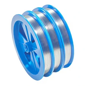 Aluminum Bonding Wire
Aluminum bonding wire offers good conductivity, mechanical properties, and a wide range of wire diameters. It is widely used in power semiconductor wedge bonding connections. Compared to fine metal wires used in precision IC packaging, aluminum wire is better suited for power devices requiring higher current carrying capacity. Typical applications cover IGBT modules, power semiconductor devices, and automotive electronic modules.
-
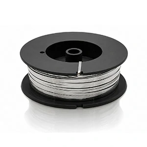 Aluminum Bonding Ribbon
Aluminum bonding ribbon features a rectangular cross-section. Compared to round bonding wires, it provides a larger connection area, making it suitable for high-current power electronics packaging. Its stable electrical connection capability makes it widely used in new energy and high-power module fields. Typical applications cover electric vehicle power modules, inverter systems, and new energy power electronics equipment.
Core Differences Between Ball Bonding and Wedge Bonding
Both ball bonding and wedge bonding are common bonding processes in semiconductor packaging. However, due to differences in connection methods, tool structures, and applicable materials, they are primarily applied to different types of semiconductor products.
Ball bonding is typically used for applications requiring high-density connections and fine-pitch packaging. Common materials include gold and copper bonding wires, mainly applied to precision semiconductor packaging such as ICs and memory devices.
Wedge bonding is more suitable for power electronics applications requiring higher current carrying capacity and larger connection areas. It commonly uses aluminum bonding wire or aluminum ribbon and is widely applied to IGBTs, power modules, and new energy electronic devices.
| Comparison Item | Ball Bonding | Wedge Bonding | Comparison Item |
| Bond Shape | Ball + Stitch Bond | Flat Wedge Bond | Bond Shape |
| Main Tool | Capillary Tool | Wedge Tool | Main Tool |
| Common Materials | Gold Bonding Wire (Au Wire), Copper Bonding Wire (Cu Wire) | Aluminum Bonding Wire (Al Wire), Aluminum Bonding Ribbon (Al Ribbon) | Common Materials |
| Wire Size | Primarily uses fine wire specifications | Supports fine wires to large-size wires/ribbons | Wire Size |
| Main Advantage | Suitable for fine-pitch, high-density packaging | Suitable for high-current connections and power applications | Main Advantage |
| Typical Applications | IC packaging, memory devices, LEDs, precision electronic components | Power semiconductors, IGBT modules, electric vehicle electronics | Typical Applications |
How to choose the right bonding method based on application
In semiconductor packaging, the choice of bonding method mainly depends on the chip type, package structure, and electrical performance requirements. Different applications correspond to different bonding processes and material systems.
The following table helps customers quickly understand the matching relationship between common applications and bonding materials.
| Application Area | Typical Product | Recommended Bonding Method | Common Material |
| IC Packaging | Integrated Circuits, Logic Chips | Ball Bonding |
Gold Bonding Wire Copper Bonding Wire |
| Memory Packaging | Memory Device | Ball Bonding |
Gold Bonding Wire Copper Bonding Wire |
| LED Packaging | LED Chip | Ball Bonding | Gold Bonding Wire |
| RF Devices | RF Device | Ball Bonding |
Gold Bonding Wire Copper Bonding Wire |
| IGBT Modules | Power Module | Wedge Bonding | Aluminum Bonding Wire |
| New Energy Vehicle Electronics | EV Power Electronics | Wedge Bonding |
Aluminum Bonding Wire Aluminum Ribbon |
| Inverter Systems | Inverter Module | Wedge Bonding | Aluminum Ribbon |
| High-Power Electronic Equipment | Power Semiconductor | Wedge Bonding |
Aluminum Wire Aluminum Ribbon |
| Application Area | Typical Product | Recommended Bonding Method | Common Material |
| IC Packaging | Integrated Circuits, Logic Chips | Ball Bonding | Gold Bonding Wire Copper Bonding Wire |
| Memory Packaging | Memory Device | Ball Bonding | Gold Bonding Wire Copper Bonding Wire |
| LED Packaging | LED Chip | Ball Bonding | Gold Bonding Wire |
| RF Devices | RF Device | Ball Bonding | Gold Bonding Wire Copper Bonding Wire |
| IGBT Modules | Power Module | Wedge Bonding | Aluminum Bonding Wire |
| New Energy Vehicle Electronics | EV Power Electronics | Wedge Bonding | Aluminum Bonding Wire Aluminum Ribbon |
| Inverter Systems | Inverter Module | Wedge Bonding | Aluminum Ribbon |
| High-Power Electronic Equipment | Power Semiconductor | Wedge Bonding | Aluminum Wire Aluminum Ribbon |
FAQ
What is the difference between ball bonding and wedge bonding?
The main differences between Ball Bonding and Wedge Bonding lie in the connection method, tools used, and applicable materials.
Ball bonding completes the connection by forming a metal ball. It typically uses gold or copper bonding wires and is mainly used for high-density semiconductor packaging such as ICs and memory devices.
Wedge bonding forms the connection using a wedge-shaped tool and ultrasonic energy. It typically uses aluminum bonding wire or aluminum ribbon and is mainly applied in power semiconductors and high-current packaging fields.
Which bonding method is used for power semiconductor devices?
Power semiconductor devices typically use Wedge Bonding.
Since power devices need to carry large currents and operate in long-term thermal cycling environments, Aluminum Bonding Wire and Aluminum Bonding Ribbon are often used for wedge bonding connections.
Typical applications include:
IGBT Modules
Power Modules
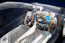
Electric Vehicle Electronic Systems
Is aluminum bonding wire suitable for ball bonding?
Under normal circumstances, aluminum bonding wire is mainly used for Wedge Bonding applications rather than Ball Bonding.
This is because aluminum wire is typically used in power semiconductor packaging requiring larger wire diameters and high current carrying capacity, while ball bonding is mainly used for fine-pitch, high-density IC packaging, often employing gold or copper wires.
What factors should be considered when selecting bonding materials?
When selecting semiconductor bonding materials—especially when comparing gold, silver, copper, and aluminum bonding wires—you need to comprehensively consider:
- Application Type
- Bonding Method
- Wire Diameter / Ribbon Dimensions
- Mechanical Properties
- Electrical Requirements
Different package structures and application environments have different requirements for bonding materials, which need to be matched according to specific needs.
Selecting the Right Bonding Material for Semiconductor Packaging
In semiconductor packaging, the appropriate bonding material needs to be selected based on application requirements, package structure, and bonding process.
- Ball Bonding is mainly used for fine-pitch, high-density semiconductor packaging, commonly employing Gold Bonding Wire and Copper Bonding Wire.
- Wedge Bonding is widely used in the field of power semiconductors, typically employing Aluminum Bonding Wire and Aluminum Bonding Ribbon.
The selection of bonding materials requires comprehensive judgment combining package form, current requirements, size requirements, and application environment.
By understanding the matching relationship between different bonding methods and materials, customers can more effectively select bonding material solutions that suit their semiconductor application needs.