In micro-channel aluminum tubes for automotive heat exchangers and ultra-wide microchannel tube for EV battery cooling, the key challenge is not extrusion feasibility, but stable mass production—consistent yield rate, hermeticity, and weldability.
Chalco supplies pre-validated, process-tuned extrusion dies ready for trial extrusion—not just theoretical drawings. Existing dies cover micro-channel flat tubes for radiators/HVAC (≤ 60 mm) and integrated cooling channels for battery systems (60–253 mm). Samples can be obtained without upfront tooling fees for pressure testing, brazing evaluation, and assembly verification—typically 2–4 weeks faster and saving thousands of dollars versus new die development.
- Yield Rate & Hermeticity: Multi-port thin-wall extrusion dies have already run in volume production with consistent channel formation, uniform wall thickness, and dense weld seams—meeting pressure resistance and vacuum brazing requirements.
- Low Prototyping Barrier: Trial-extruding micro-channel tube samples directly from existing dies enables assembly and pressure validation without mold cost.
- Ultra-Wide Solution: For > 253 mm integrated battery cooling plates, a joint-tooling route is available, targeting fewer weld points, fewer leakage risks, and lower scrap rates.
Quick Navigation:
Radiator / HVAC Micro-Channel Flat Tubes (≤60 mm)
The following micro-channel aluminum tube extrusion dies supplied by Chalco have been validated in mass production and are mainly used for automotive radiators, condensers, evaporators, heat pumps, and HVAC coils, typically with widths below 60 mm. All listed dies can be trial-extruded to obtain real samples without upfront tooling fees, supporting pressure testing, vacuum brazing, and assembly fit verification.
Match your target profile based on W×H dimensions, channel count, and recommended alloy.
| Mold No. | W×H/mm | Hole | Illustration | Recommended Alloy |
| HL20-22 | 22*4 | 12 |
 |
1xxx / 3xxx |
| HL20-25-1 | 25*6 | 3 |
 |
1xxx / 3xxx |
| HL20-25-2 | 25*6 | 3 |
 |
1xxx / 3xxx |
| HL20-25-3 | 25*6 | 8 |
 |
1xxx / 3xxx |
| HL20-25-4 | 25.5*3 | 4 |
 |
1xxx / 3xxx |
| HL20-26 | 26*6 | 3 |
 |
1xxx / 3xxx |
| HL20-27 | 27*8 | 6 |
 |
1xxx / 3xxx |
| HL30-32-1 | 32*3.5 | 7 |
 |
1xxx / 3xxx |
| HL30-32-2 | 32*5 | 5 |
 |
1xxx / 3xxx |
| HL30-32-3 | 32*6.4 | 6 |
 |
1xxx / 3xxx |
| HL30-35 | 35.5*3 | 6 |
 |
1xxx / 3xxx |
| HL30-36 | 36*3 | 11 |
 |
1xxx / 3xxx |
| HL30-38-1 | 38*6.5 | 3 |
 |
1xxx / 3xxx |
| HL30-38-2 | 38.6*7 | 6 |
 |
1xxx / 3xxx |
| HL30-39 | 39.2*4.5 | 10 |
 |
1xxx / 3xxx |
| HL40-40-1 | 40*5 | 7 |
 |
1xxx / 3xxx |
| HL40-40-2 | 40*7 | 6 |
 |
1xxx / 3xxx |
| HL40-40-3 | 40*8 | 7 |
 |
1xxx / 3xxx |
| HL40-45 | 45*4 | 7 |
 |
1xxx / 3xxx |
| HL40-47 | 47*4.5 | 7 |
 |
1xxx / 3xxx |
| HL40-48-1 | 48*5 | 8 |
 |
1xxx / 3xxx |
| HL40-48-2 | 48*9.4 | 8 |
 |
1xxx / 3xxx |
| HL40-49-1 | 49*6.1 | 9 |
 |
1xxx / 3xxx |
| HL40-49-2 | 49*6.9 | 8 |
 |
1xxx / 3xxx |
| HL40-49-3 | 49.2*7 | 8 |
 |
1xxx / 3xxx |
| HL40-49-4 | 49.5*4.5 | 12 |
 |
1xxx / 3xxx |
| HL50-53-1 | 53*5 | 15 |
 |
1xxx / 3xxx |
| HL50-53-2 | 53*6.5 | 4 |
 |
1xxx / 3xxx |
| HL50-53-3 | 53*6.5 | 7 |
 |
1xxx / 3xxx |
| HL50-53-4 | 53*7.5 | 16 |
 |
1xxx / 3xxx |
| HL50-54 | 54.7*8 | 12 |
 |
1xxx / 3xxx |
| HL50-56-1 | 56*10.5 | 7 |
 |
1xxx / 3xxx |
| HL50-56-2 | 56*10.5 | 9 |
 |
1xxx / 3xxx |
| HL50-56-3 | 56*10.5 | 10 |
 |
1xxx / 3xxx |
| HL50-57 | 57*6.6 | 9 |
 |
1xxx / 3xxx |
| HL50-58-1 | 58*4.6 | 10 |
 |
1xxx / 3xxx |
| HL50-58-2 | 58*4.6 | 10 |
 |
1xxx / 3xxx |
| HL50-58-3 | 58*6.5 | 7 |
 |
1xxx / 3xxx |
| HL60-60-1 | 60*4.5 | 15 |
 |
1xxx / 3xxx |
| HL60-60-2 | 60*7 | 9 |
 |
1xxx / 3xxx |
Why Choose Chalco's Micro-Channel Flat Tube Dies (≤60 mm)
- Hermeticity & Brazing Pass Rate: These thin-wall, multi-port dies (≈0.3 mm wall) have proven volume production with simultaneous channel fill, uniform wall thickness, accurate mandrel alignment, and dense weld seams—passing vacuum brazing and high-pressure cycling tests with low leakage and minimal batch scrap risk.
- Low-Risk Start, Fast Sampling: Dies labeled In-stock / Open can usually be trial-extruded immediately to obtain micro-channel tube samples for pressure, brazing, and assembly verification—typically 2–4 weeks faster than new-die development, and without advance tooling cost.
- Industry-Mainstream Alloy Path: Recommended alloys are concentrated in 1xxx / 3xxx series, offering high thermal conductivity, brazability, and corrosion resistance—aligned with radiator and HVAC industry norms, reducing repeated material approval cycles.
- Direct Use for Internal Project Kickoff: What you receive is not a profile drawing but actual extruded tube segments, ready to weld into existing heat exchanger prototypes for trial fit, leak testing, and jig validation—suitable for internal project justification or OEM submission.
Cooling Plates / Wide Multi-Cavity Cooling Channels (60–253 mm)
Quick Jump: 60–98 (with tolerance diagrams) | 100–253 (wide multi-cavity reference)
The following extrusion dies are designed for EV battery cooling plates, coolant circuits, and thermal management modules, covering 60–253 mm wide integrated multi-cavity profiles. Chalco provides in-stock, process-tuned dies that can be trial-extruded into full-width samples for flow, pressure-drop, and thermal validation—typically 2–4 weeks faster and without upfront tooling fees compared to new-die development.
In-Stock Die List (60–98 mm)
Match your target profile based on W×H, cavity count, and recommended alloy (3xxx / 6xxx depending on application). This section includes drawings with tolerance markings to help pre-evaluate assembly fit, flatness requirements, and cycling pressure capability.
| Mold No. | W×H/mm | Hole | Illustration | Recommended Alloy |
| HL60-61 | 61*7 | 10 |
 |
3xxx / 6xxx |
| HL60-62-1 | 62*6 | 8 |
 |
3xxx / 6xxx |
| HL60-62-2 | 62*6 | 10 |
 |
3xxx / 6xxx |
| HL60-62-3 | 62*8 | 13 |
 |
3xxx / 6xxx |
| HL60-62-4 | 62.05*6.1 | 12 |
 |
3xxx / 6xxx |
| HL60-64-1 | 64*5 | 11 |
 |
3xxx / 6xxx |
| HL60-64-2 | 64*5 | 13 |
 |
3xxx / 6xxx |
| HL60-64-3 | 64*6 | 14 |
 |
3xxx / 6xxx |
| HL60-64-4 | 64*6.6 | 16 |
 |
3xxx / 6xxx |
| HL60-64-5 | 64*8.1 | 12 |
 |
3xxx / 6xxx |
| HL60-64-6 | 64*8.08 | 10 |
 |
3xxx / 6xxx |
| HL60-65-1 | 65*4 | 14 |
 |
3xxx / 6xxx |
| HL60-65-2 | 65*6.4 | 18 |
 |
3xxx / 6xxx |
| HL60-65-3 | 65*6.4 | 18 |
 |
3xxx / 6xxx |
| HL60-65-4 | 65*6.6 | 10 |
 |
3xxx / 6xxx |
| HL60-66 | 66*8 | 11 |
 |
3xxx / 6xxx |
| HL60-68 | 68*9 | 15 |
 |
3xxx / 6xxx |
| HL70-70-1 | 70*6.5 | 8 |
 |
3xxx / 6xxx |
| HL70-70-2 | 70*7.8 | 12 |
 |
3xxx / 6xxx |
| HL70-70-3 | 70*10 | 12 |
 |
3xxx / 6xxx |
| HL70-70-4 | 70*10 | 6 |
 |
3xxx / 6xxx |
| HL70-70-5 | 70*10.5 | 12 |
 |
3xxx / 6xxx |
| HL70-72 | 72*6 | 16 |
 |
3xxx / 6xxx |
| HL70-75 | 75*5 | 8 |
 |
3xxx / 6xxx |
| HL70-76 | 76*6.5 | 8 |
 |
3xxx / 6xxx |
| HL80-80-1 | 80*5 | 16 |
 |
3xxx / 6xxx |
| HL80-80-2 | 80*6 | 11 |
 |
3xxx / 6xxx |
| HL80-85 | 85*7 | 12 |
 |
3xxx / 6xxx |
| HL90-90 | 90*6.9 | 14 |
 |
3xxx / 6xxx |
| HL90-98 | 98*11 | 17 |
 |
3xxx / 6xxx |
In-Stock Die List (100–253 mm)
The following 100–253 mm wide multi-cavity cooling channel / cooling plate extrusion profiles are shown as simplified cross-section diagrams for readability. For detailed tolerances, recommended alloys, flatness control ranges, and full technical drawings, please contact us.
| Mold No. | W×H/mm | Hole | Illustration |
| HL100-100-1 | 100*4 | 18 |
 |
| HL100-100-2 | 100*4.5 | 29 |
 |
| HL100-100-3 | 100*6.9 | 15 |
 |
| HL100-100-4 | 100*7 | 12 |
 |
| HL100-100-5 | 100*15.5 | 18 |
 |
| HL100-104-1 | 104*6.4 | 23 |
 |
| HL100-104-2 | 104*6.4 | 30 |
 |
| HL110-111 | 111*2.5 | 19 |
 |
| HL110-114-1 | 114.5*1.5 | 27 |
 |
| HL110-114-2 | 114.5*1.5 | 44 |
 |
| HL110-114-3 | 114.61*3.9 | 42 |
 |
| HL120-120-1 | 120*4 | 32 |
 |
| HL120-120-2 | 120*4 | 33 |
 |
| HL120-120-3 | 120*4 | 47 |
 |
| HL120-121 | 121.5*1.5 | 23 |
 |
| HL120-125 | 125*2.7 | 38 |
 |
| HL130-134 | 134*5 | 30 |
 |
| HL130-137 | 137.8*2.3 | 35 |
 |
| HL130-139 | 139.7*3.74 | 75 |
 |
| HL140-148 | 148.5*14.8 | 11 |
 |
| HL150-150 | 150*8 | 17 |
 |
| HL180-186 | 186*6 | 9 |
 |
| HL190-190-1 | 190*6.5 | 9 |
 |
| HL190-190-2 | 190*8.5 | 9 |
 |
| HL200-200 | 200*2 | 24 |
 |
| HL200-201 | 201.25*1.5 | 46 |
 |
| HL200-203-1 | 203.25*1.5 | 56 |
 |
| HL200-203-2 | 203*7 | 67 |
 |
| HL200-203-3 | 203*12 | 67 |
 |
| HL210-219-1 | 219*5 | 40 |
 |
| HL210-219-2 | 219.8*5 | 73 |
 |
| HL230-234 | 234*5 | 71 |
 |
| HL250-253 | 253*4 | 15 |
 |
Why Use Chalco's 60–253 mm Wide Multi-Cavity Cooling Channel Dies
- Flatness / Distortion Control: Wide profiles benefit from compensated die port design and reinforced support to minimize warpage and edge collapse, ensuring cooling plates / housings assemble with full surface contact.
- Uniform Channels & Pressure Capability: Flow distribution and internal rib thickness are balanced according to pressure-drop and pressure-resistance targets—supporting flow rate, thermal uniformity, and cyclic pressure testing.
- Fewer Weld Points = Fewer Leak Points: A single-piece wide multi-cavity profile replaces multiple narrow tubes and weld seams—significantly reducing sealing interfaces, assembly time, and after-sales leakage risk.
- Alloy and Strength Window: Default 3xxx series for thermal conductivity, brazability, and corrosion resistance; 6xxx series (such as 6061/6063) can be evaluated when higher rigidity or structural load is required.
- Basic Post-Processing Capability: Sample parts can be supplied with fixed-length cutting, end-face alignment, datum holes or reference edges, plus optional flux pre-coating, zinc-spray, or protective coatings—enabling early testing of brazability, pressure/airtightness, flatness, and interface conformity.
Ultra-Wide Cooling Plates / One-Piece Battery Trays Extrusion (>253 mm)
When the width exceeds ≈253 mm, the requirement is no longer a micro-channel tube, but a functional one-piece component—such as a battery cooling plate, battery tray, cooling circuit housing, serpentine flow channel plate, or angled-port tube. These applications demand a wide, thin-wall, multi-cavity single extrusion blank, instead of welding dozens of small tubes together.


For >253 mm, Chalco adopts a joint-tooling approach—conducting manufacturability evaluation based on your target profile and advancing toward >300 mm and >400 mm one-piece cooling plates / trays while balancing flatness, rigidity, pressure capacity, and sealing life.
What Chalco Can Do for >253 mm One-Piece Cooling Channels
One-Piece Forming With Dramatically Fewer Welds
By extruding an entire cooling plate / tray / circuit housing as a single multi-cavity component, dozens of weld seams and sealing points are eliminated. Leakage risk, rework risk, and after-sales failures are reduced in parallel—supporting OEM validation with confidence.
Flatness and Rigidity Controlled Together
Ultra-wide thin-wall profiles are not "just a large extrusion." Port design, support, and shaping strategies are engineered around flatness, edge collapse, twist, and warpage—so the part can fit directly against the battery pack or cooling module, without extensive post-straightening.
Channel Path & Pressure Capability Co-Evaluated to Your Conditions
We don't stop at sending a cross-section snapshot. We jointly review channel routing, wall-thickness balance, target pressure-drop, cyclic pressure life, and airtightness—ensuring the multi-cavity profile not only "looks right," but can run thermal management and pressure-cycle tests on a real bench.
Application-Based Alloy Selection
For load-bearing or structural components (trays, housings), 6xxx series aluminum can be evaluated for rigidity and strength. For thermally driven areas, 3xxx series can be specified for conductivity, corrosion resistance, and brazability. No one-size-fits-all—we propose a function-zoned materials window.
Note: >253 mm belongs to a custom range with no standard in-stock dies. The workflow follows Drawings → Process Review → Dedicated Die Design → Sampling, targeting maximum integration with fewer welds and sealing points.
Machining / Forming Capabilities
To ensure samples arrive in a state that is fixture-ready, connection-ready, and pressure-test-ready, rather than raw extrusion blanks.
Core CNC Machining Operations
Chalco can provide fixed-length cutting, end-face alignment, chamfering, datum hole drilling, and simple locating grooves—supporting clamping, sealing, coupling, and pressure testing, rather than supplying parts that can only be viewed by hand.
Micro-Channel Flat Tube Bending / Forming
For micro-channel aluminum tubes used in radiators and HVAC, bending or forming can be performed within controlled radii to minimize rib collapse, bursting, and excessive thinning—enabling assembly-space validation and brazing mock-ups.


Reserved Assembly Reference Surfaces
For 60–253 mm wide multi-cavity channels and >253 mm cooling plates / tray profiles, samples can retain or be machined with simple clamping faces, locating edges, and reference holes—allowing flatness measurement, sealing-pressure testing, and fixture positioning.


Surface Condition / Brazing Preparation / Corrosion Protection
To help samples move directly into welding validation, fluid cycling tests, and interface conformity checks—without getting stuck in pre-treatment.
Brazing Preparation
For heat-exchange profiles such as micro-channel flat tubes, brazing-friendly surface conditions (flux pre-coating / brazing-compatible treatments) can be supplied to support vacuum brazing trials—verifying "bonds securely, seals reliably, no leakage after brazing."
Basic Anti-Corrosion / Anti-Permeation Layers
For wide multi-cavity cooling channels, cooling plates, and tray components, common protective surface treatments (anti-corrosion coatings, zinc-spray layers, etc.) can be applied based on testing conditions—supporting preliminary durability assessment under coolant cycling, salt spray, and environmental exposure.
Flatness and Surface Roughness Control on Contact Faces
For areas that contact the battery module / battery pack, flatness and roughness can be controlled to evaluate thermal contact performance and sealing quality—without requiring large-scale secondary machining.
Basic Testing and Verification
To provide engineering, quality, and project stakeholders with measurable data—not conceptual drawings.
Airtightness / Pressure / Pressure-Cycle Testing
Pressure durability, leakage inspection, and cyclic-pressure testing can be performed on micro-channel tubes, wide multi-cavity channels, and cooling plate samples—verifying weld-seam density, channel connectivity, and sealing behavior under pressure.
Flatness / Edge Stability Measurement
For 60–253 mm width channels and >253 mm cooling plates / trays, overall flatness, edge collapse, twist, and warpage can be measured—assessing whether parts can mate to installation surfaces without further shaping.
Wall-Thickness and Internal Channel Distribution Sampling
Outer wall thickness, rib thickness, and channel opening uniformity can be sampled to establish real wall-distribution and channel-uniformity baselines—used to judge pressure capacity, pressure-drop consistency, and lifecycle risk.
Clamping / Interface Accessibility Validation
For samples with basic CNC work, datum hole positions and locating edges can be validated for clamping, gasket compression, temporary fittings, and bench testing—supporting internal pressure tests, coolant flow, and thermal cycling.
Featured Case Studies
Case 01|Passenger Vehicle Thermal Systems · Micro-Channel Flat Tubes (≤60 mm)
Customer: European passenger vehicle thermal management Tier-1 supplier (automotive condenser / heat pump modules)
Application: Micro-channel flat tubes used as the main body of condensers / heat pump heat exchangers
Specification:
- Outer size 25.0 mm × 2.0 mm
- 16 parallel channels
- Outer wall ≈ 0.30 mm, internal ribs ≈ 0.32 mm
- Typical 3xxx series aluminum (brazable, high thermal conductivity)
Die / Tolerances:
Matched Chalco's in-stock micro-channel flat tube die (≤60 mm range) — no new tooling required. Post-extrusion straightening and channel-fill inspection completed.
- Outer width: 25.0 mm ±0.05 mm
- Wall-thickness deviation: ≤0.03 mm
- Straightness: ≤0.2 mm/m
- No rib collapse, no bursting, continuous internal cavity formation
Surface / Delivery Condition:
Cut to approx 600 mm straight tube samples; end-face precision cut with deburring and chamfering for vacuum brazing trials. Final coating not applied (customer uses own flux and coating system).
Outcome:
Customer ran joint brazing and airtightness tests in their small-batch vacuum brazing furnace—no visible leakage after brazing.
By using an existing die instead of opening a dedicated new one, first-round validation required zero tooling cost, and sample delivery was completed within 5 days, accelerating their original "new die + trial extrusion" plan by ≈2–3 weeks.
Case 02|EV Battery Cooling Module Supplier · Wide Multi-Cavity Cooling Channels
Customer: North American EV battery cooling system supplier (module-level cooling plates / coolant circuits)
Application: One-piece multi-cavity cooling channel extrusion used for coolant pressure-drop and flow distribution testing
Specification:
- Outer size ≈120 mm × 6.0 mm
- 8 main channels + internal reinforcing ribs
- Outer wall ≈ 1.6 mm, rib ≈ 1.8 mm
- Primarily 3xxx series aluminum for thermal conductivity, brazability, and corrosion resistance
- Target cyclic pressure ≤2 bar
Die / Tolerances:
Matched Chalco's in-stock wide multi-cavity die (100–253 mm range) — no immediate new tooling; extrusion parameters and die balance were micro-adjusted.
- Outer width: 120.0 mm ±0.10 mm
- Channel wall deviation: ≤0.07 mm
- Flatness: ≤0.35 mm / 120 mm — ensuring proper mating to cooling module housing without edge lifting
Surface / Delivery Condition:
Two straight plate samples approx 800 mm long; precision-cut ends, deburred; side reference edge milled and two φ6 test holes added at designated points for clamping, sealing, and pressure testing. Final anti-corrosion layer not applied (customer will anodize or surface-treat later).
Outcome:
Customer completed real coolant pressure-drop measurement and 2 bar pressure / leakage testing. The plate maintained flatness within the test fixture with no significant twist or edge collapse, meeting their module-level thermal management targets.
Using existing wide multi-cavity tooling, the customer advanced their internal thermal feasibility milestone by ≈3 weeks, presenting real multi-cavity extruded hardware instead of a 2D cross-section drawing to the OEM thermal management team.
Case 03|New Energy Vehicle Platform · One-Piece Battery Tray / Cooling Plate Bottom Panel
Customer: Battery systems team of a South American new energy commercial vehicle platform
Application: Pack-level battery tray bottom cooling + structural integration, replacing "tray + serpentine tubes + numerous welds" with a single multi-cavity extrusion
Target Design Specification:
- Target width ≈320 mm
- Multi-cavity serpentine / angled-port cooling passages integrated within the same plate
- Outer wall target ≈2.2 mm, internal ribs 1.5–1.8 mm
- Customer expected 6xxx series alloys (e.g., 6061/6063) for higher rigidity and structural strength while retaining thermal capacity
- Plate must both dissipate heat and carry structural load
Die / Tolerances:
No in-stock die. Customer supplied full 3D model and Chalco initiated >253 mm joint-tooling evaluation:
- Confirmed overall 300+ mm width within our one-piece extrusion capability (can advance toward 500 mm class)
- Identified deep/thin channel regions prone to collapse—recommended additional support ribs or local thickening
- Suggested keeping primary load zone ≥2.2 mm wall thickness, with local thinning in cooling zones to avoid excess mass
- Recommended reference edges for later shaping and flatness verification to ensure mating to battery pack
Surface / Delivery Condition:
This stage did not deliver a full tray. Based on the reviewed die-port concept, Chalco first extruded localized "window-section" samples (scaled functional segment), then performed pressure, initial airtightness, and flatness checks, marking areas requiring reinforcement.
Outcome:
For the first time, customer stakeholders could present a real multi-cavity one-piece extrusion segment, not a PPT graphic.
Based on test results, they reduced over 20 weld / sealing points in the original tray concept and passed the internal milestone for "feasibility of one-piece cooling tray"—proceeding to next-stage dedicated die design without committing full-scale tooling cost.
One-Stop HVAC Heat Exchangers & EV Battery Thermal Management Supply
Aluminum for Automotive / HVAC Heat Exchanger Systems
-
") Micro-Channel Multi-Port Flat Tubes (MPE Tubes)
Micro-Channel Multi-Port Flat Tubes (MPE Tubes)Thin-wall multi-port extrusions (typically 8–60 mm wide with dozens of individual channels) used in condensers, evaporators, heat-pump heat exchangers, and e-drive cooling modules. The goal is to maximize heat-transfer area per unit volume while maintaining hermeticity and leak-free performance after vacuum brazing.
Brazable Thin-Wall Multi-Port High Heat-Transfer Area -
") Condenser Headers / Manifold Tubes (Header Tubes)
Condenser Headers / Manifold Tubes (Header Tubes)Formed by high-frequency welding of clad aluminum strip into round, flat, or channel-shaped tubes, with optional multiple inlets/outlets or port patterns. Their role is to collect and distribute flow across multiple micro-channel tubes in parallel, with key requirements of dimensional stability, pressure resistance, and low leakage after brazing.
Flow Distribution Pressure-Tight Sealing Weldable -
 Brazing Clad Sheet & Fin Stock
Composite brazing sheets and strips such as 4045/3003 and 4343/3003, combining wettability, corrosion resistance, and structural strength. Hydrophilic / hydrophobic coated fin stock helps drain condensate and slow down corrosion, ideal for heat pumps, air-conditioning units, and energy storage cooling systems.
Composite Brazing Layer Corrosion Resistance Lightweight -
 Aluminum Tubes for Heat Exchangers & HVAC Piping
Aluminum tubes and piping grades matched to refrigerant loops and heat-pump circuits, including alloys and tempers that are expandable, bendable, and brazable. Focus points are corrosion resistance, sealing capability, and dimensional stability—so customers can route the entire system circuit directly on the unit.
Bendable Corrosion-Resistant Piping System Line Routing
Aluminum for EV Battery Thermal Management & Cell Systems
-
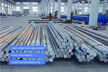
 Panoramic View of Aluminum for EV Batteries
Looking at 1xxx / 3xxx / 5xxx / 6xxx alloys from a full-pack perspective: which alloys are best for cooling circuits, which for housings / trays and load-bearing parts, and which for conductive / thermal paths. This is often the first question OEMs and pack suppliers ask during material selection.
3xxx for Thermal Conductivity 6xxx for Strength Pack-Level Weight Reduction -
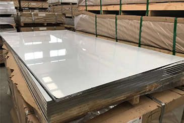
 Aluminum Sheet & Strip for Battery Housings / Trays
Aluminum sheet for battery pack housings, tray floors, module frames, and partitions—focusing on lightweight, weldability, impact resistance, and corrosion resistance. Cutting and datum-edge preparation can be tailored to the customer's pack design and bolt layout.
Lightweight Impact-Resistant Weldable -
 Aluminum for Battery Liquid Cooling Plates
For module- and pack-level cooling plates, the focus is on integrating channels, pressure resistance, airtightness, and flatness into a single aluminum structure—commonly using 3xxx / 4xxx brazing clad plates.
Liquid Cooling Channels Pressure & Airtightness Pack Thermal Management -
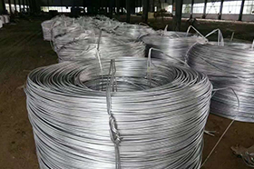
 Aluminum Foil Current Collectors for Battery Cells
High-purity aluminum foil for lithium-ion battery positive electrode collectors, requiring high conductivity, tight thickness tolerance, and stable flatness for coating, winding, and stacking.
High Conductivity Tight Thickness Tolerance Winding & Stacking Friendly -
 Carbon-Coated Aluminum Foil
Applied with a uniform conductive carbon layer to reduce interface resistance, improve coating adhesion, and mitigate hot spots and dendrite risks—ideal for fast-charging, long-cycle EV and energy-storage batteries.
Fast-Charge Friendly Low Interface Resistance Long Cycle Life
Frequently Asked Questions (FAQ)
Do You Have Existing Dies, or Do We Need to Open a New One First?
Yes. For micro-channel flat tubes (≤60 mm) used in radiators / HVAC and for wide multi-cavity cooling channels (60–253 mm) used in EV battery cooling plates, we have in-stock extrusion dies. You can trial extrude and get real samples for validation without paying tooling fees.
Profiles >253 mm belong to the custom range and require joint evaluation before tooling.
Can We Get Samples First for Airtightness, Brazing, Pressure-Drop, and Flatness Testing?
Yes. We can extrude short tube / plate segments from existing dies, cut them to length, and apply basic CNC alignment / chamfering / datum edges—so you can run brazability, pressure / leakage, pressure-drop, and flatness / contact conformity tests.
This usually allows you to enter validation 2–4 weeks earlier than "open a new die and debug first."
What Is the Minimum Order Quantity (MOQ)? Will You Force a Large Order Up Front?
It depends on the stage:
- Sample validation stage → per piece / per segment, not by tonnage
- Pilot run → one extrusion batch, typically a few hundred kg up to ~1 ton
- Mass production → MOQ defined by tonnage + specification
For >253 mm ultra-wide tray projects, MOQ is not discussed until manufacturability is confirmed.
Can We Send Our Own Cross-Section / Drawing to Make a Dedicated Die?
Yes. This is a dedicated-spec route. We first evaluate manufacturability (wall thickness, channel structure, pressure resistance, flatness, alloy feasibility) to ensure it is not physically un-extrudable or low-yield, then proceed with dedicated die design and sampling.
This path is typical for >253 mm one-piece cooling plates / trays, or when you require exclusive geometry.
How Do You Select Alloys? Can We Use Automotive-Grade Alloys?
- Micro-channel flat tubes and small multi-port profiles → 3xxx series (high thermal conductivity, brazable, corrosion resistant; ideal for vacuum brazing validation)
- Battery cooling plates / wide multi-cavity channels → primarily 3xxx, balanced with strength and flatness
- Trays, housings, full-pack bottom plates → evaluated toward 6xxx series (e.g., 6061 / 6063) for rigidity and strength, while considering thermal performance and sealing life
We provide application-based alloy recommendations, rather than leaving you to guess.
Will You Machine Parts to "Vehicle-Assembly Ready" Condition?
We provide engineering validation level, not full vehicle final assembly level.
Meaning:
- Fixed-length cutting, end-face alignment, chamfering
- Datum hole positions and reference edges
- Controlled-radius bending samples for micro-channel flat tubes
- Clamping / sealing reference faces for wide cooling plates and tray segments
Full vehicle assembly interfaces / flanges are normally finalized by the system integrator, not promised casually.
How Do You Prove It Doesn't Leak, Won't Warp, and Can Hold Pressure?
We can perform:
- Pressure durability / leakage testing / pressure-cycle testing
- Flatness, edge collapse, twist / warpage measurements
Especially for 60–253 mm cooling plates and >253 mm tray segments, confirming whether they can mate to battery modules / packs.
These data points are usually enough for internal approval or the first technical meeting with OEM thermal teams.
Do You Serve Both Heat Exchanger Customers and Battery Cooling Plate / Tray Customers?
Yes, but via different paths:
- Heat exchanger / HVAC customers typically use ≤60 mm micro-channel flat tubes and headers — focus on brazed hermeticity and no leakage
- Battery cooling plate / tray customers typically use 60–253 mm wide multi-cavity or >253 mm one-piece trays — focus on flatness, pressure-drop path, pressure durability, and structural rigidity
We apply scenario-specific support (in-stock trial extrusion vs joint-tooling), rather than a one-size-fits-all pitch.