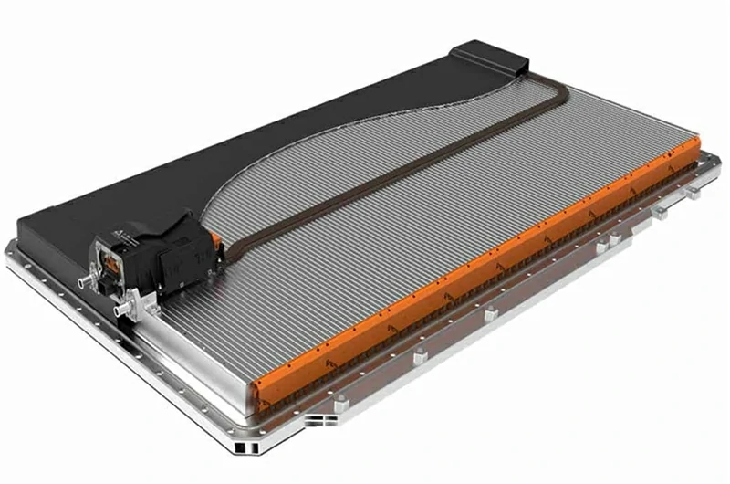
Why integrate microchannel aluminum flat tubes into BESS separators?
BESS separator = structure + cooling + safety
Embedding MPE (Multi Port Extruded) microchannel aluminum flat tubes directly into the separator delivers.
Thermal management
High surface area channels + high thermal conductivity aluminum → ~30% better heat transfer vs traditional cold plates.
TRP (Thermal Runaway Propagation) blocking
Works with flame-retardant/insulation layers to conduct heat and block fire—providing component-level data for UL9540A certification.
Weight reduction & assembly simplification
Eliminates separate cold plates and complex piping; the BESS separator cooling channel becomes part of the structure, speeding up assembly.
Standardization + fast customization
Common 11/13/19-port profiles in stock, cut to drawing/vacuum brazed; CAD/CFD feedback within 24h.
Specifications & Technical Parameters (Standard Profiles)
Dimensions & Structure Parameters
| Model Code | W (mm) | H (mm) | Ports N | Dh (mm) | t (mm) | Zn Coating (g/m²) | Stock Lengths (mm) |
| MPE-20×2.0-11 | 20 | 2 | 11 | 1.1 | 1.2 | 5±2 | 3000 / 6000 |
| MPE-22×1.8-13 | 22 | 1.8 | 13 | 0.95 | 1.1 | 7±2 | 3000 / 6000 |
| MPE-25×2.2-19 | 25 | 2.2 | 19 | 0.85 | 1.4 | 7±2 | 3000 / 6000 |
| MPE-28×2.5-19H | 28 | 2.5 | 19 | 0.9 | 1.6 | 10±2 | 4000 / 6000 |
| MPE-18×1.5-11L | 18 | 1.5 | 11 | 1.2 | 1 | 5±2 | 3000 |
| MPE-32×3.0-19R | 32 | 3 | 19 | 1 | 1.6 | 10±2 | 4000 / 6000 |
| MPE-24×2.0-13A | 24 | 2 | 13 | 1.05 | 1.3 | 7±2 | 3000 / 6000 |
| MPE-30×2.2-19S | 30 | 2.2 | 19 | 0.88 | 1.5 | 10±2 | 4000 / 6000 |
Performance & Processing
| Model Code | Burst Pressure (MPa) | ΔP @ 60 L·min⁻¹ Single Plate (MPa) | Min Bend Radius Rmin (mm) |
| MPE-20×2.0-11 | 4.8 | 0.015 | ≥10 |
| MPE-22×1.8-13 | 5.2 | 0.014 | ≥9 |
| MPE-25×2.2-19 | 5.6 | 0.013 | ≥11 |
| MPE-28×2.5-19H | 6 | 0.012 | ≥13 |
| MPE-18×1.5-11L | 4.5 | 0.017 | ≥8 |
| MPE-32×3.0-19R | 6.2 | 0.011 | ≥15 |
| MPE-24×2.0-13A | 5 | 0.014 | ≥10 |
| MPE-30×2.2-19S | 5.8 | 0.012 | ≥12 |
Special Requirements for Flat Tubes in Energy Storage Baffle Applications
| Requirement Point | Background Reason | Flat Tube Requirements | Our Solution |
| Thermal Runaway Blocking (UL9540A) | Large single-cell capacity with concentrated heat generation | Wall thickness 1.0–1.6 mm; redundant weld design | Rounded weld seams, burst/leak test reports, flame-retardant layer bonding compatibility tests |
| Large-Area Flatness (≤0.3 mm/m) | Large cell contact surface; warping = poor thermal contact | Symmetrical tube layout, aspect ratio w/t ≤ 25 | FEM pre-compensation, anti-deformation fixtures, brazing process control documentation |
| Low ΔP & Low Pump Power | Long-term operational energy efficiency sensitivity | Dh 0.8–1.2 mm, 11/13/19-hole cross section | ΔP–Q test curves, CFD optimization recommendations, pump selection reference table |
| Corrosion/Environmental Resistance | EG water/insulating oil, salt spray conditions | Zinc spray 5±2 / 7±2 / 10±2 g·m⁻² + coating | 1,000 h NSS test report, compatibility charts, surface treatment options |
| Complete Certification Documentation | PED, UL1973/9540A, IEC62619 | Full burst, fatigue, ΔP–Q, corrosion documentation | Master report templates + project-specific variation tests, shipment-ready documentation package |
Selecting Section & Key Parameters
| Parameter | Recommended Range (BESS) | Impact Indicators | Design Notes |
| Number of holes N | 11 / 13 / 19 | ΔP, temperature uniformity | Increasing N → reduces flow velocity → lowers ΔP; excessive holes raise cost and clogging risk. 11/13/19 covers most application needs. |
| Hydraulic diameter Dh | 0.8–1.2 mm | ΔP, Re, heat transfer | Re ≈ 300–1200 (laminar/transitional) for controllable pump power; locally >2000 to enhance heat transfer. |
| Wall thickness t | 1.0–1.6 mm | Burst strength, fatigue, safety factor | Greater t improves safety but slightly reduces thermal conductivity; select based on TRP/pressure requirements. |
| Overall dimensions w×h | 18–32 mm × 1–3 mm | Flatness, stiffness | Keep w/t ≤ 25 to prevent buckling; match thickness to total baffle thickness. |
| Zinc spray weight | 5±2 / 7±2 / 10±2 g·m⁻² | Brazing wetting, corrosion resistance | For coastal/salt spray projects, select 10±2; clean surface after brazing to aid subsequent flame-retardant coating. |
| Surface treatment | Anodizing / Nano-coating / Bare tube | Bonding, corrosion protection | Choose treatment compatible with bonding/flame-retardant processes to avoid peeling or contamination. |
Quick selection: Send ΔT target, allowed ΔP, coolant, and plate size → CFD/ΔP–Q preliminary in 24h.
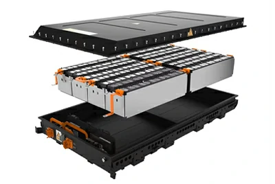
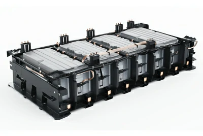
Six Key Procurement Criteria for BESS Separators
UL9540A support: ≥4× burst margin, >10⁷ fatigue cycles, leak/fire data.
30%+ higher heat transfer & lower ΔP.
2-week shipment for standard profiles, ≤5 free samples by DHL in 3–5 days.
CAD/CFD files within 24h for internal review.
Full documentation: CE, PED, UL, IEC62619, RoHS/REACH/SDS, MTC, PQR/WPS.
Flatness ≤0.3 mm/m & w/t ≤25.: Ensure close contact with the electrode and smooth assembly.
Four Processes for Integrating Flat Tubes into Baffles
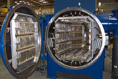
CNC Slotting + Vacuum Brazing (Embedded Type): Slot width allowance of +0.05–0.15 mm; ensure uniform zinc spray; use anti-deformation fixtures. Apply a brazing layer at the slot bottom to prevent cold joints.
Sandwich Structure: Upper and lower plates with intermediate flat tubes/ribs; control the brazing curve to prevent bulging or collapse; match flat tube wall thickness with rib dimensions to increase stiffness.
Extruded Profile + Flat Tube Insert Welding: Extrude ribs into the main profile and locally insert/weld flat tubes; reserve a weld seam buffer zone and perform post-weld heat treatment to avoid fatigue weak points in the heat-affected zone (HAZ).
One-Piece Bending: Minimum bending radius Rmin ≥ 3–5× t; use internal mandrels or segmented bending when necessary. Verify via FEM analysis that the inner wall at the bend does not collapse.
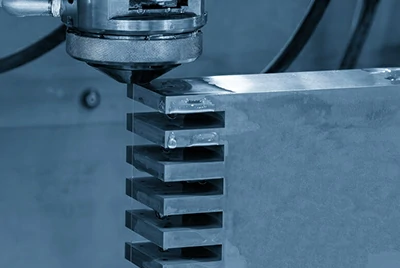
Risk Mitigation Measures
Weld leak prevention: optimized brazing, CT scan, 100% helium test.
Temperature uniformity: CFD-optimized porting, cleaning, filtration.
Flatness control: symmetrical layout, FEM, anti-deformation jigs.
Pitting resistance: Zn + coating, compatibility testing.
We provide: ΔP–Q curves, CFD files, burst/pressure/fatigue reports, corrosion reports, MTC, PQR/WPS, RoHS/REACH/SDS.
Delivery & Cost Control
Lead time: Standard profile + process → 2 weeks; custom (new die) → 4–5 weeks.
Cost strategies: Use standard profiles, unify Zn/coating specs, leverage master test reports, batch brazing.
FAQ
Q: How does it help UL9540A?
A: Component-level test data supports faster certification.
Q: Is Zn coating mandatory?
A: Recommended for large plates in vacuum brazing; alternatives possible.
Q: Can the same section be used for oil cooling?
A: Yes, with coating/seal compatibility validation.
Q: Fastest for small-batch projects?
A: Standard profile + embedded process → 3–5 days DHL samples.
Q: Can you provide CAD/CFD files?
A: Yes, under NDA.
Contact Us
Send CAD sketch, ΔT target, allowed ΔP, coolant, and annual usage to: sale@chalcoaluminum.com
2h: Engineering section suggestion & preliminary results
24h: CAD/CFD model + ΔP–Q estimate + quotation
≤5 free samples: DHL 3–5 days
Global delivery: 2-week standard lead time, DDP to NA/EU available


