For CoB-LED reflector cups and mixing chambers: L95 maintains ≈95% ±2 total reflectance at 450/550/625 nm with ≈5% ±2 controlled diffuse reflectance, and passes 150 °C/1000 h and 85 °C/85% RH/1000 h tests.
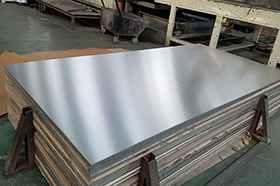
What is L95 high-reflectance mirror-finish aluminum?
L95 is a high-performance aluminum mirror material engineered for CoB-LED applications under high-temperature and demanding environmental conditions. It can boost luminous efficacy across the LED spectrum by about 4%. Above 425 nm it maintains very stable reflectance. At typical CoB-LED wavelengths—around 450 nm (blue LED chips), 550 nm (white-LED phosphor), and 625 nm (yellow-LED phosphor)—L95 delivers≈95% ±2 total reflectance with≈5% ±2 controlled diffuse reflectance.

Dimensional Tolerances
| Item | Specification |
| Thickness tolerance (coil & sheet) [mm] | ±8% of nominal thickness |
| Coil width tolerance [mm] | +2.00 / −0.00 |
| Slit coil width tolerance [mm] | +0.06 / −0.00 |
| Coil longitudinal curvature | ≤1 per 1000 mm length |
| Sheet size [mm] | Width < 1250 • Length < 4000 |
| Sheet size tolerance [mm] | +0.50 / −0.00 (<500 mm) • +1.50 / −0.00 (500–2000 mm) • +2.50 / −0.00 (2000–4000 mm) |
| Flatness (%S ≤ 3 mm, adjustable upon request) | <1% |
Mechanical Properties
| Property | Specification |
| Tensile strength [N/mm²] | ≥ 140 |
| Yield strength [N/mm²] | ≥ 120 |
| Elongation A50 [%] | ≥ 2 |
| Uniformity across width [%] | ± 2.5 |
| Uniformity along length [%] | ± 5.0 |
| Elongation [%] | ≥ 1 |
| Forming bend radius | ≥ 1.5 × strip thickness |
Physical Properties
| Property | Specification |
| Density [g/cm³] | 2.7 |
| Coefficient of thermal expansion [10⁻⁶·K⁻¹] | 23.1 |
| Specific heat capacity [J/(kg·K)] | 900 |
| Effective thermal conductivity [W/(m·K)] | > 170 |
Optical Properties
| Property | Specification |
| Total reflectance (Y/D65/2°) [%] | 94 ± 1 |
| Diffuse reflectance (Y/D65/2°) [%] | ≤ 5 |
| Reflectance at 450 nm [%] | ≥ 93 |
| Specular reflectance (60° incidence) [%] | ≥ 89 |
| Color (CIELAB D65 10°) | L*: 98 ± 1 • a*: −0.2 to +0.2 • b*: −0.2 to +0.2 |
| Iridescence | No visibly noticeable iridescence |
Durability Tests
The following table summarizes the durability test results for the product.
| Test Item | Result |
| Neutral salt spray test (chromed sample / 72 h / allowed ΔY% < 1%) | ΔY% ≤ 0.5% |
| Cross-cut adhesion test (no more than 2/100 areas showing peeling) | 0/100 areas showed adhesion failure |
| High-temperature adhesive test (180 °C / 2 h / allowed ΔY% < 1%) | ΔY% ≤ 0.5% |
| High-temperature baking test (250 °C / 100 h / allowed ΔY% < 1%) | ΔY% ≤ 0.5% |
| High-temperature baking test (150 °C / 1000 h / allowed ΔY% < 1%) | ΔY% ≤ 0.5% |
| Artificial climate aging (40 °C, 95% RH, 400 h) | ΔY% ≤ 1.0% |
| Artificial climate aging (85 °C, 85% RH, 1000 h) | ΔY% ≤ 2.0% |
| UV aging test (18 kWh/m² / allowed ΔY% < 1%) | ΔY% ≤ 0.5% |
| Severe sulfur-containing atmosphere test (>15 ppm H₂S, 40 °C – 95% RH, 115 h) | ΔY% ≤ 1.5% |
Neutral Salt Spray Test (Coated Sample / 72 Hours / ΔY% < 1%)

High-Temperature Baking Test (150 °C / 1000 Hours / ΔY% < 1%)

Artificial Climate Chamber Test (85 °C – 85% RH / 1000 Hours / ΔY% < 2%)

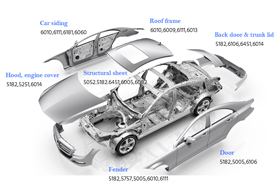
Application Scenarios
Track Spotlights
Target beam angles: 10° / 15° / 24° / 36°
Performance: UGR ≤ 16 / 19, Ra ≥ 90 / 95, SDCM ≤ 3, clean beam edges without "onion-ring” artifacts.
Use L95 reflectors ("mirror-dominant + ≈5% diffuse”). Recommended geometry: H/D ≈ 0.9–1.3, secondary reflection angle 20°–40°. Add 3–5 mm anti-glare rings or honeycomb grids.
Assembly tolerance: aperture = fastener diameter + 0.10–0.20 mm; tightening torque: M2: 0.15–0.2 N·m / M3: 0.4–0.6 N·m. Maintain 0.2–0.5 mm floating gap.
Reliability: passed 150 °C / 1000 h and 85 °C–85% RH / 1000 h tests; total luminous flux retention ≥ 98% after 1000 h operation.


Downlights
Typical beam angles: 24° / 36° / 60°, UGR ≤ 19 / 22. Designed for long-duration operation with stable chromaticity and luminous flux.
Reflector chamber uses L95, with 1–2 mm chamfer or micro-bead matte finish at cup edge for better uniformity.
Recommended geometry: H/D ≈ 0.6–1.0, secondary reflection angle 25°–55°, paired with matte black anti-glare ring.
Protection film should be removed within 30 minutes before assembly. Performance targets: SDCM ≤ 3, Salt spray 72 h ΔY% < 1%.
Use three-point alignment + large-area thermal contact for effective heat coupling.
Wall Washers
Target: uniform wall illumination U₀ ≥ 0.6–0.7, suitable for semi-outdoor / humid / salt-fog conditions.
Light guide or mixing chamber uses L95 ("mirror + ≈5% diffuse”) with a white reflector patch on the near-wall side.
Recommended geometry: H ≈ 0.8–1.2× window width, secondary reflection angle 40°–60°.
Ensure precise edge cutting of shutters and baffles; optional micro-prism diffuser for beam shaping.
Reliability: Salt spray 72 h ΔY% < 1%, thermal–humidity cycling (85–85) verified. Provide U₀ simulation and IES photometric data for validation.


Exhibition Halls
Color rendering Ra ≥ 95, evaluate Rf / Rg per TM-30, UGR ≤ 16 / 19, strict control of color drift and UV output.
L95 optimized for 450 / 550 / 625 nm wavelengths ensures stable spectral balance.
Use deep-cup + anti-glare ring design; controlled diffuse ≈5% improves uniformity. Mirror surface remains unroughened; optional honeycomb or white film to reduce glare.
Remove protective film and assemble within 30 minutes in a ≥100k clean zone.
Monitor ΔCCT / ΔDUV and TM-30 consistency over lifetime; provide three beam options + IES files.
High-Humidity
Used in environments with continuous humidity, heat, or airborne pollutants where flux and color stability must be maintained without dark spots.
Select L95 reflector (proven 85 °C–85% RH / 1000 h ΔY% < 2%).
Mechanical assembly with minimal adhesive use; integrate with 304/316 stainless parts using passivation and electrical insulation.
Seal with neutral silicone / low-VOC compounds, validated by atomization tests.
Add matte black anti-glare ring and optional anti-fog / oil-resistant front lens.
Reliability: passed 72 h salt spray and pollution–cleaning cycles, luminous flux retention ≥ 98%.
Manufacturing Processes
Blanking / Punching / Trimming & Deburring
Total die clearance: 6%–10% of t (thin stock: 6%–8%; thick stock: 8%–10%).
Cutting edge hardness HRC ≥ 58, mirror-polished; concentricity ≤ 0.02 mm.
Keep the protective film throughout; prioritize fine blanking/compound dies.
Laser: limit heat input; plasma/flame: not used.
After deburring, burr height < 0.1 mm or < 10%·t (whichever is stricter).
Chamfer R0.1–0.2.
Visual inspection at 500 lx / 400 mm and 10× loupe sampling must pass.


Bending / Flanging / Small-R Corner Forming
Minimum inside bend radius: generally R ≥ 0.5·t; for mirror finish use R ≥ 0.7·t for safety.
Flange height H ≥ 1.0–1.2·D; edge/holespacing ≥ 1.5–2.0·t.
Bend springback compensation 1.5–2.0°; die surface Ra ≤ 0.2 μm.
Cover the bend zone with PTFE/PU soft pads to avoid imprints.
Prefer one-shot forming; if multi-pass, per-pass deformation ≤ 50% with ≥ 30 min rest between passes; use EVA/PE soft interlayers during transfer.
Punching / Slotting / Micro-dot Glare Control
Hole center to edge ≥ 1.5D or 2.0·t (take the larger); hole pitch ≥ 2.0D.
For Ø < 1.0 mm, use micro-needle + vacuum scrap extraction.
Ensure thorough chip evacuation and guided tooling to prevent galling, re-adhesion, and mirror scratching.
For anti-glare microstructures, use white-layer patch embossing or chemical etching.
Do not roughen the L95 front surface to avoid irreversible reflectance loss.


Adhesive Bonding / Riveting / Screwed Joints
Adhesives: low-VOC, low-fogging systems.
PSA (VHB-type): allow 24 h dwell to cure; structural adhesives: neutral-cure/low-halogen; sealant: neutral silicone with fogging/temperature qualification.
Aperture = fastener OD + 0.10–0.20 mm; use spring washers or nylon washers.
Reference torque: M2: 0.15–0.20 N·m; M3: 0.4–0.6 N·m (fixture-verified).
Reserve 0.2–0.5 mm floating gap along the long side or radial direction.
Provide electrical insulation at dissimilar-metal contacts; prefer passivated 304/316 hardware.
Surface Protection / Cleaning & Film Removal
Wear powder-free, silicone-free gloves; work on microfiber/ESD benches.
Cleaning: lint-free wipes with IPA/DI = 1:1; for heavy soil, neutral detergent first, then DI rinse.
Do not use strong alkalis, strong oxidizers, chlorinated ketones, or aromatic solvents.
Schedule film removal at final assembly and install within 30 min in ≥ ISO Class 100,000 local clean conditions.
Appearance criteria: at 500 lx/400 mm straight-on view no defects; at 45°, light marks ≤ 0.1 mm and not affecting the beam.
Thermal Processes / Baking / Coating
Reliability boundary 150 °C × 1000 h.
Process temperature spikes ≤ 160 °C and ≤ 30 min; long-term operating temperature ≤ 120 °C.
Before bonding/sealing, low-temp de-outgassing of cavity and reflector at 70–90 °C × 1–2 h.
Avoid prolonged high-temperature exposure of the mirror face.
No coating on the mirror front; for backside local light-blocking, use low-fog matte black with proper masking.
FAQs (Q&A)
Q1: What is L95's reflectance and which bands matter most?
A: It maintains ≈95% ±2 total reflectance at ~450/550/625 nm and is stable over a broad band ≥ 425 nm. The surface is mirror-dominant with ≈5% ±2 controlled diffuse to mitigate glare and improve uniformity.
Q2: How is long-term reliability? What about yellowing control?
A: 150 °C × 1000 h ΔY% < 1%; 85 °C/85% RH × 1000 h ΔY% < 2%; neutral salt spray 72 h ΔY% < 1%. Lumen output and color tolerance remain more stable.
Q3: How is it different from general mirror aluminum?
A: L95 is target-optimized at 450/550/625 nm and emphasizes ΔY% stability after 1000 h of high-temp/humidity stress. General mirror aluminum is broader-spectrum without LED peak targeting or defined durability boundaries.
Q4: Is the surface purely specular or diffuse? Will it cause glare?
A: It is mirror-dominant with ~5% ±2 controlled diffuse. This preserves efficiency while improving spot uniformity and glare control.
Q5: Which luminaires and scenarios fit best?
A: CoB reflector cups, light-guide/mixing cavities, track lights, wall-washers, down/spotlights. It is particularly recommended for high-power, sealed, or high-humidity environments.
Q6: What are the key "hard” processing parameters?
A: Punch clearance 6%–10%·t; bend radius R ≥ 0.5·t (mirror recommended R ≥ 0.7·t); spacing edge ≥ 1.5D or 2.0·t, pitch ≥ 2.0D; burr < 0.1 mm or < 10%·t; chamfer R0.1–0.2.
Q7: How should assembly and adhesives be chosen?
A: Prefer low-VOC systems: VHB-type PSA (assemble after 24 h), neutral-cure/low-halogen structural adhesives, neutral silicone for sealing. Aperture = fastener + 0.10–0.20 mm; torque M2: 0.15–0.20 N·m, M3: 0.4–0.6 N·m with fixture verification.
Q8: How to set thermal and environmental limits?
A: Process spikes ≤ 160 °C and ≤ 30 min; long-term operation ≤ 120 °C; pre-lighting 70–90 °C × 1–2 h bake-out to reduce VOC risk.
Q9: Do you provide samples and test reports?
A: Yes—optical samples, integrating-sphere reflectance reports (400–700 nm curves), and reliability data. We can assist with photometric tuning (UGR/uniformity/IES).
Q10: Can you customize and prototype to drawings?
A: Yes—stamping/bending/punching/film-lamination to print. When process parameters or material batches change, follow re-sampling with CPK, optical, and aging comparison deliverables.