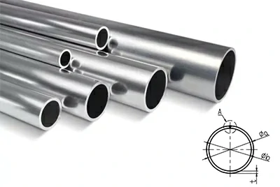
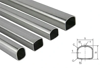
Henan Chalco supplies Copper Pillar Pins, copper pin arrays, and Pin Modules, supporting round, square, or rectangular cross-sections, pin height, pitch, and array layout according to package structure and drawing requirements. The products are mainly used for vertical interconnects between packaging layers in SiP, PMIC, and 2.5D/3D structures. Supply can range from Individual Pins to pre-arranged arrays and modular formats to match different package layouts and assembly methods.
- Product Forms: Individual Pin | Pin Array | Pin Module
- Common Shapes: Round | Square / Rectangular | Straight
- Applications: SiP | PMIC | 2.5D / 3D Packaging
What Is a Copper Pillar Pin?
A Copper Pillar Pin is a preformed micro copper pillar pin that can be handled, arranged, and assembled as an individual component. It is typically positioned between package substrates, module layers, or other packaging structures to establish vertical electrical connections. Different pin heights and array layouts can be used to accommodate interlayer spacing and package design.
The main difference between a Copper Pillar Pin and a Cu Pillar Bump lies in how they are formed and supplied: a Copper Pillar Pin is a discrete preformed component, while a Cu Pillar Bump is typically formed directly on the wafer- or die-side pad structure. Copper Standoffs / Spacers, by contrast, are used mainly for PCB or mechanical support rather than micro-package interconnection.
| Type | Product Form | Typical Position |
| Copper Pillar Pin | Individual Pin, Array, or Module | Between substrates, modules, or packaging layers |
| Cu Pillar Bump | Formed on Wafer / Die | Between Die and substrate, RDL, or interposer |
| Copper Standoff | Mechanical support component | PCB or general electronic assembly |
For round copper pillars, square copper pillars, and other columnar copper interconnect structures, see the parent Copper Pillar product page.
Individual Copper Pillar Pins, Pin Arrays, and Pin Modules
Copper Pillar Pins can be supplied as individual pins, arrays, or modules depending on the downstream arrangement and assembly method. The main difference is whether pre-arrangement and modular organization have already been completed.
-
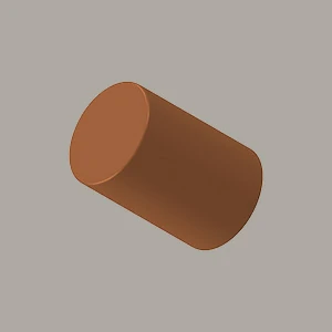 Individual Copper Pillar Pin
A micro copper pillar pin manufactured and supplied as an individual part. It can use a round, square, or rectangular cross-section, with diameter or width, length, and end geometry defined by drawing.
-
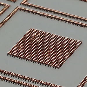 Pin Array - Copper Pillar Pin Array
Multiple copper pillar pins arranged at target positions and pitch. Pin count, distribution area, and positional relationships are defined according to the package layout.
-
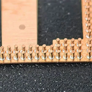 Pin Module
A modular structure built on a Pin Array, with multiple pins arranged and positioned according to the target layout. Module outline, pin count, pitch, and array area can be confirmed according to the package structure.
Individual Pin → Pin Array → Pin Module
Regardless of the supply form, product selection starts with the shape and critical dimensions of an individual pin, followed by the array or module configuration.
Copper Pillar Pin Specifications
Copper Pillar Pins are typically defined by cross-sectional shape, diameter or width, length, pitch, material, and supply form. Required pin height, spacing, and layout vary by package structure and can be further confirmed from the drawing.
| Specification Item | Typical Specification / Reference Range |
| Product Form | Individual Pin / Pin Array / Pin Module |
| Cross-Sectional Shape | Round / Square / Rectangular |
| Pin Type | Straight; special end geometries can be confirmed from the drawing |
| Round Pin Diameter | φ0.06–2.0 mm |
| Round Pin Length | 0.10–6.0 mm |
| Square / Rectangular Cross-Section | Reference sizes: 0.20×0.20, 0.33×0.23, 0.35×0.35, 0.40×0.30, 0.40×0.40, 0.70×0.30, 0.80×0.50 mm |
| Square / Rectangular Pin Length | Approx. 0.20–6.0 mm |
| Pitch | Confirmed according to pin size, quantity, and array layout |
| Material | Copper; specific grade to be confirmed from the drawing |
| Surface Condition | To be confirmed according to the drawing and connection interface requirements |
| Supply Form | Individual / Array / Module |
*Round pins can be defined by diameter D, length L, and pitch P; square or rectangular pins can be defined by width W, thickness T, length L, and pitch P.
After the basic specifications are defined, the package location, interlayer height, and assembly method should also be considered to determine product fit.
Where Are Copper Pillar Pins Used in Advanced Semiconductor Packaging?
Copper Pillar Pins are mainly used for vertical interconnects between upper and lower substrates or between different packaging layers. In addition to providing electrical paths, these preformed pins can use defined pin heights and array layouts to accommodate interlayer spacing and component clearance within the package.
SiP Module
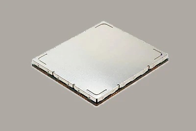
In SiP (System in Package), Copper Pillar Pins can be positioned between upper and lower package substrates to establish vertical electrical connections while maintaining the required interlayer height. Pin length, pitch, and distribution area should be determined together with the substrate layout and internal component positions.
PMIC Module
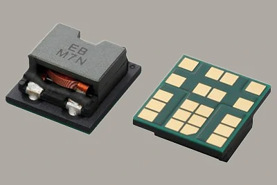
Some PMIC modules need to reserve space between upper and lower substrates for taller components such as inductors. Copper Pillar Pins can provide the interlayer connection while creating the required spacing, so pin height and layout should be matched to component height and package structure.
2.5D / 3D SiP
When interlayer connections must be established at multiple fixed positions, Copper Pillar Pins can be organized as Pin Arrays or Pin Modules for multi-point vertical interconnection. Pin height, pitch, array position, and downstream assembly method should all be considered.
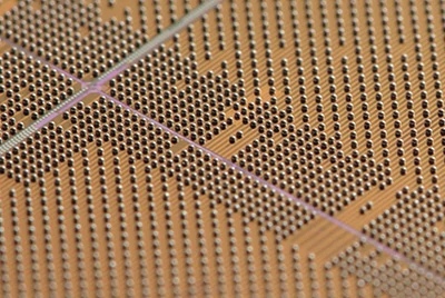
Copper Pillar Pins are only one interconnect route used in advanced IC packaging. Depending on the package structure, wire bonding, ribbon bonding, or other interconnect methods may also be used. See our IC Packaging Interconnect Solutions for a broader overview.
Individual Pin, Pin Array, or Pin Module: Which Should You Choose?
After defining the pin shape and dimensions, the next decision is which supply form best fits downstream assembly. The three options do not represent a simple performance ranking; the choice mainly depends on the customer's existing feeding, arranging, and positioning capabilities as well as the package layout.
| Customer Assembly Condition | More Suitable Option |
| Existing single-pin feeding, arranging, or insertion capability | Individual Pin |
| Fixed-pitch pre-arrangement required | Pin Array |
| Multiple pins need to be positioned or assembled as a unit | Pin Module |
| Assembly route still under development | Evaluate based on package structure and equipment conditions |
Individual Pins offer greater flexibility for downstream arranging and positioning. When the number of interconnect points increases and the pitch and positional relationships are already defined, a Pin Array can be considered. If downstream operations require the pins to be handled, positioned, or assembled as a group, a Pin Module may be more suitable.
For micro copper pillars, meeting individual-pin dimensional requirements does not necessarily mean the delivered form will work with existing equipment. During sample evaluation, pin count, pitch, array layout, and the customer's feeding and assembly method should therefore be confirmed together, avoiding a situation where the parts meet specification but cannot be integrated smoothly into the downstream process.
How Are Copper Pillar Pins Typically Manufactured?
These preformed micro copper pillars are typically produced from copper wire or shaped wire. Precision cut-to-length operations create the basic pillar body, while enlarged heads or other special end geometries may require additional cold forming or cold heading depending on the geometry.
Copper Wire / Shaped Wire → Precision Cutting → End Forming as Required → End-Face and Burr Finishing → Cleaning → Surface Treatment if Required → Inspection
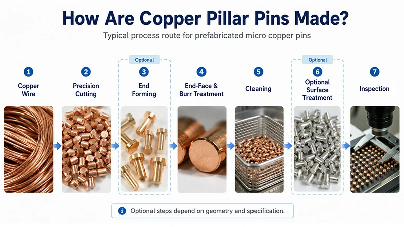
For Straight Pins, key controls include cross-sectional dimensions, length, and end-face consistency. Special end geometries also require control of the formed dimensions. Customers generally need to define the final geometry and critical dimensions on the drawing, after which the corresponding manufacturing route can be determined based on the part structure.
Why Does Array Quality Matter Even When Individual Pins Meet Requirements?
When Copper Pillar Pins are supplied as Pin Arrays or Pin Modules rather than as individual pins, acceptance criteria expand from individual-pin dimensions to the positional relationship of the entire array. The two supply forms therefore require quality controls at different levels.
| Single Pin | Pin Array / Pin Module |
| Diameter / Width | Pitch Consistency |
| Length | Missing Pins |
| Straightness | Pin Tilt |
| End Face & Burrs | Orientation / Attitude Consistency (if applicable) |
| Surface Condition | Coplanarity |
For individual pins, length, straightness, and end-face deviations can affect downstream positioning and connection. At the Array or Module level, missing pins, tilted pins, or insufficient coplanarity must also be avoided. For square, rectangular, or other asymmetric pins, orientation / attitude consistency should also be considered. Even when every individual pin meets dimensional requirements, array-level deviations can still affect downstream assembly.
Therefore, when purchasing Arrays or Modules, the drawing or acceptance criteria should define array-level requirements such as pitch, position, and coplanarity in addition to individual-pin dimensions, so that sample approval and subsequent lot acceptance use consistent criteria.
When Should Copper Pillar Pins Be Considered?
Copper Pillar Pins, Solder Balls, and Cu Pillar Bumps (Plated Cu Pillars) represent different interconnect and assembly routes. Selection should be based first on whether the existing package structure, target interconnect height, and manufacturing process fit the chosen interconnect format rather than on a simple ranking of which option is better.
| Project Condition | More Suitable Option |
| Need a discrete preformed pillar interconnect supplied as a single Pin, Array, or Module | Copper Pillar Pins |
| Mature solder ball placement and reflow process already in place, and existing connection height meets design needs | Solder Balls |
| Copper pillar needs to be formed directly on the Wafer / Die side and integrated with the Bumping process | Cu Pillar Bump / Plated Cu Pillar |
Copper Pillar Pins may be evaluated when the package requires a defined interlayer height set by the length of a preformed pin, or when vertical interconnects need to enter assembly as Individual Pins, pre-arranged Arrays, or Modules. For projects already using stable Solder Ball or Cu Pillar Bumping processes that meet structural and reliability requirements, any change in interconnect route should be weighed against the cost of redesign and requalification.
From Drawing to Sample Validation
A Copper Pillar Pin project can begin with an existing drawing, package cross-section, or key dimensions. A complete package process file is not required for the initial discussion.
Drawing & Application Review → Pin Form & Specification Confirmation → Sample & Dimensional Confirmation → Customer Assembly & Reliability Validation
The initial review focuses on pin location, shape, dimensions, and the required supply form—Individual Pin, Pin Array, or Pin Module. At the sample stage, product dimensions, array characteristics, and agreed acceptance items are confirmed first.
The customer then completes assembly and reliability validation using the actual substrate, interface, equipment, and packaging conditions. Critical specifications established during sample evaluation should, where possible, be carried forward into subsequent lot acceptance.
Copper Pillar Pins FAQ
Can Special End Geometries or Non-Standard Shapes Be Evaluated?
Yes. In addition to common Round, Square / Rectangular, and Straight Pin formats, special end geometries can be evaluated from the drawing when required by the connection, positioning, or assembly structure.
How Should Copper Pillar Pin Material and Surface Condition Be Specified?
Material and surface condition should be matched to the connection interface and downstream assembly process. These requirements should be defined in the drawing or technical specification so that sample and subsequent production acceptance use consistent criteria.
Submit Your Copper Pillar Pin Drawing
If you are developing a Copper Pillar Pin, Pin Array, or Pin Module, send your existing drawing, structural sketch, or basic dimensions to Henan Chalco. We can review the product geometry, critical dimensions, array layout, and target supply form to further confirm the project requirements.
Recommended information: Drawing / Sketch | Pin Geometry (Shape + Diameter / Width + Length, Pitch if applicable) | Supply Form (Pin / Array / Module) | Application / Package Structure | Quantity